P74x/EN FD/N
1, P742, P743
(FD) 9-
All internal communication of data from the power supply board is conducted via the output
relay board which is connected to the parallel bus.
The watchdog facility provides two output relay contacts, one normally open and one
normally closed that are driven by the processor board. These are provided to give an
indication that the relay is in a healthy state.
The power supply board incorporates inrush current limiting. This limits the peak inrush
current, during energisation, to approximately 10A.
2.8 Output relay board (standard)
The output relay board holds eight relays, six with normally open contacts and two with
changeover contacts. The relays are driven from the 22V power supply line. The relays’ state
is written to or read from using the parallel data bus.
2.9 Output relay board (High speed / High break)
The output relay board holds four relays, all normally open. The relays are driven from the
22V power supply line. The relays’ state is written to or read from using the parallel data bus.
A high speed output relay board contains a hybrid of MOSFET solid state devices (SSD) in
parallel with high capacity relay output contacts. The MOSFET has a varistor across it to
provide protection which is required when switching off inductive loads as the stored energy
in the inductor causes a reverse high voltage which could damage the MOSFET.
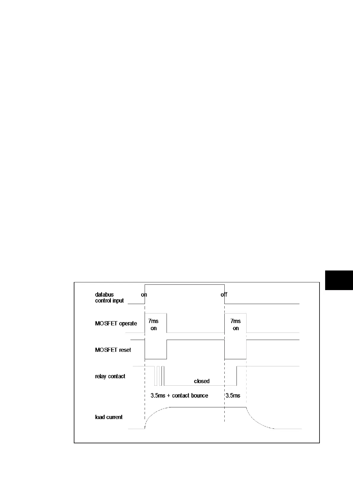
When there is a control input command to operate an output contact, the miniature relay is
operated at the same time as the SSD. The miniature relay contact closes in nominally
3.5ms and is used to carry the continuous load current; the SSD operates in <0.2ms and is
switched off after 7.5ms. When the control input resets to open the contacts, the SSD is
again turned on for 7.5ms. The miniature relay resets in nominally 3.5ms before the SSD
and so the SSD is used to break the load. The SSD absorbs the energy when breaking
inductive loads and so limits the resulting voltage surge. This contact arrangement is for
switching dc circuits only. As the SSD comes on very fast (<0.2ms) then these high break
output contacts have the added advantage of being very fast operating.
FIGURE 7: HIGH BREAK CONTACT OPERATION