x/EN PL/Na7
7-
MiCOM P74
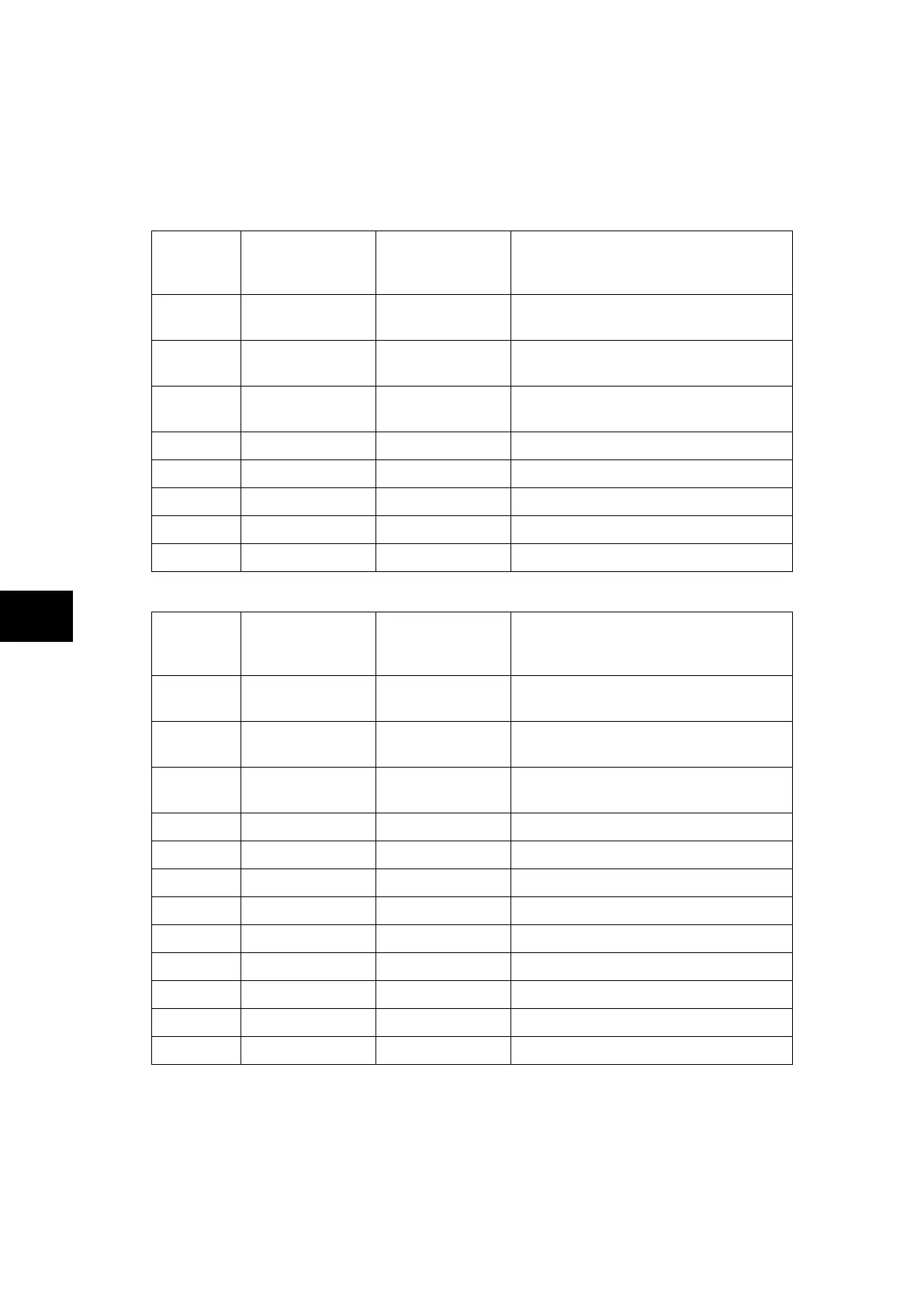
1.12 Relay output contact mapping
The default mappings for each of the relay output contacts are as shown in the following
table:
Central Unit P741:
Relay
Contact
Number
P74x Relay Text
P74x Relay
Conditioner
Function
1 Relay Label 01
Pick-up 0/0 Trip 87BB or 50BF backtrip or
overcurrent / earth fault trip (fixed)
2 Relay Label 02
Pick-up 0/0 Trip 87BB or 50BF backtrip or
overcurrent / earth fault trip (fixed)
3 Relay Label 03
Pick-up 0/0 Trip 87BB or 50BF backtrip or
overcurrent / earth fault trip (fixed)
4 Relay Label 04 Pick-up 0/0 Trip zone 1
5 Relay Label 05 Pick-up 0/0 Trip zone 2
6 Relay Label 06 Pick-up 0/0 Circuit fault or PU error
7 Relay Label 07 Pick-up 0/0 Zone 1 or zone 2 blocked
8 Relay Label 08 Pick-up 0/0 Check Zone fault
Peripheral Unit P742:
Relay
Contact
Number
P74x Relay Text
P74x Relay
Conditioner
Function
1 Relay Label 01
Pick-up 0/0 Trip 87BB or 50BF backtrip or
overcurrent / earth fault trip (fixed)
2 Relay Label 02
Pick-up 0/0 Trip 87BB or 50BF backtrip or
overcurrent / earth fault trip (fixed)
3 Relay Label 03
Pick-up 0/0 Trip 87BB or 50BF backtrip or
overcurrent / earth fault trip (fixed)
4 Relay Label 04 Pick-up 0/0 Circuit Breaker failure
5 Relay Label 05 Pick-up 0/0 Circuit Breaker failure or out of service
6 Relay Label 06 Pick-up 0/0 Circuit Breaker failure retrip
7 Relay Label 07 Pick-up 0/0 Trip or Dead Zone Fault
8 Relay Label 08 Pick-up 0/0 Circuit Breaker or Isolator status alarm
9 Relay Label 09 Pick-up 0/0 Circuit Breaker failure retrip phase A
10 Relay Label 10 Pick-up 0/0 Circuit Breaker failure retrip phase B
11 Relay Label 11 Pick-up 0/0 Circuit Breaker failure retrip phase C
12 Relay Label 12 Pick-up 0/0 Not Mapped