Na7
-
MiCOM P741, P742
5.3 Optical budgets
When using fibre optics as a method of communication the type of fibre used and the
distance between devices needs to be considered. The following table shows the optical
budgets of the communications interface.
Parameter 850nm Multi mode
Min. transmit output level (average power) -19.8dBm
Receiver sensitivity
(average power)
-25.4dBm
Optical budget 5.6dB
Less safety margin (3dB) 2.6dB 3dB
Typical cable loss 2.6dB/km
Max. transmission distance 1km
TABLE 2: OPTICAL BUDGET
The total optical budget is given by transmitter output level minus the receiver sensitivity and
will indicate the total allowable losses that can be tolerated between devices. A safety
margin of 3dB is also included in the above table. This allows for degradation of the fibre as
a result of ageing and any losses in cable joints. The remainder of the losses will come from
the fibre itself. The figures given are typical only and should only be used as a guide.
5.3.1 Main operating features
5.3.1.1 Operation modes
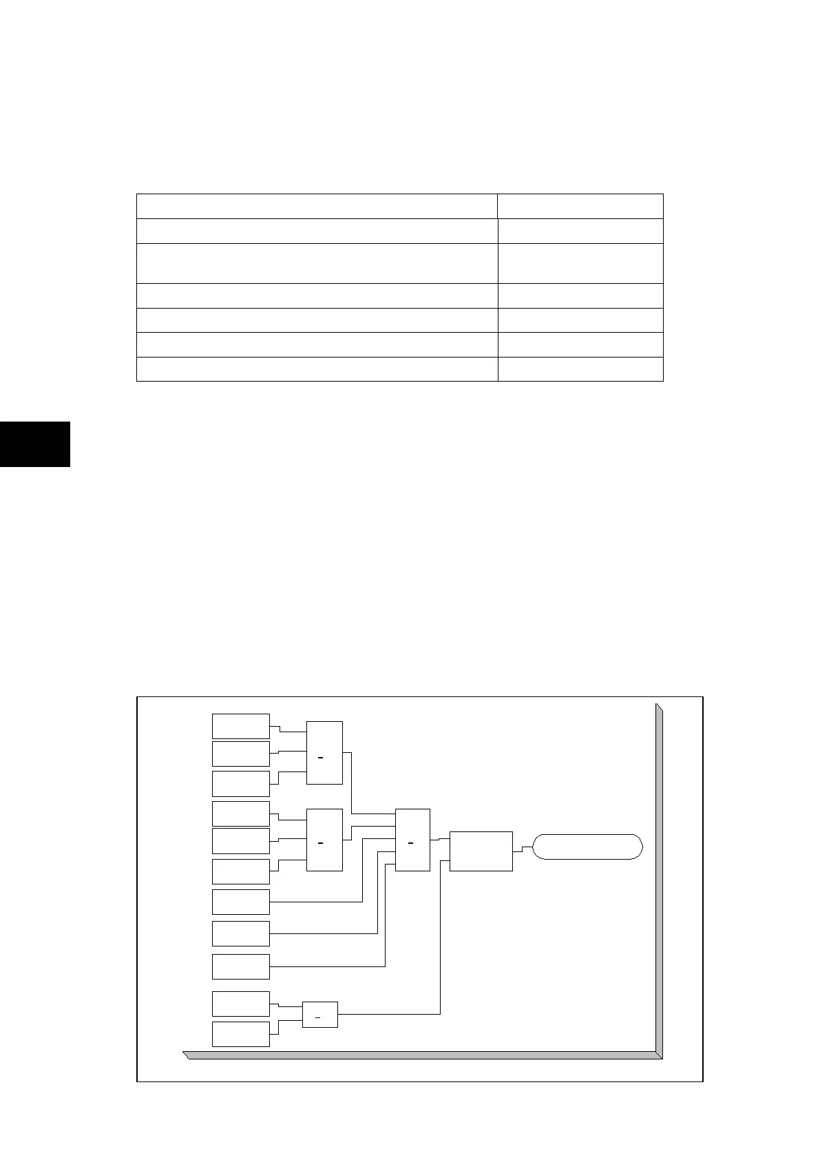
5.4 Trip LED logic
The trip LED can be reset when the flags for the last fault are displayed or via dedicated
ddbs. The flags are displayed automatically after a trip occurs, or can be selected in the fault
record menu. The reset of trip LED and the fault records is performed by pressing the key
once the fault record has been read.
TRIP LED LOGIC
Relay 1
Set
Reset
>1
Trip LED
>1 >1
>1
Relay 2
Relay 3
External Retrip
Phase A
External Retrip
Phase B
External Retrip
Phase C
Internal Retrip
Triphase
Internal Trip
Dead Zone
Fault
Reset
command
Reset
Indications
P0716ENa
FIGURE 30: TRIP LED LOGIC DIAGRAM