CM
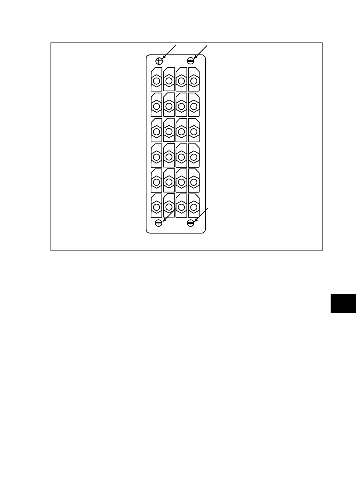
FIGURE 3: LOCATION OF SECURING SCREWS FOR HEAVY DUTY TERMINAL BLOCKS.
4.1.3 Insulation
Insulation resistance tests are only necessary during commissioning if it is required for them
to be done and they have not been performed during installation.
Isolate all wiring from the earth and test the insulation with an electronic or brushless
insulation tester at a dc voltage not exceeding 500V. Terminals of the same circuits should
be temporarily connected together.
The main groups of relay terminals are:
a) Current transformer circuits
b) Auxiliary voltage supply.
c) Field voltage output and opto-isolated control inputs.
d) Relay contacts.
e) Case earth.
The insulation resistance should be greater than 100MΩ at 500V.
On completion of the insulation resistance tests, ensure all external wiring is correctly
reconnected to the relay.
4.1.4 External wiring
Check that the external wiring is correct to the relevant relay diagram or scheme diagram.
The relay diagram number appears on the rating label under the top access cover on the
front of the relay. The corresponding connection diagram will have been supplied with the
General Electric order acknowledgement for the relay.