x/EN PL/Na7
7-
MiCOM P74
1.10 Factory default programmable scheme logic
The following section details the default settings of the PSL.
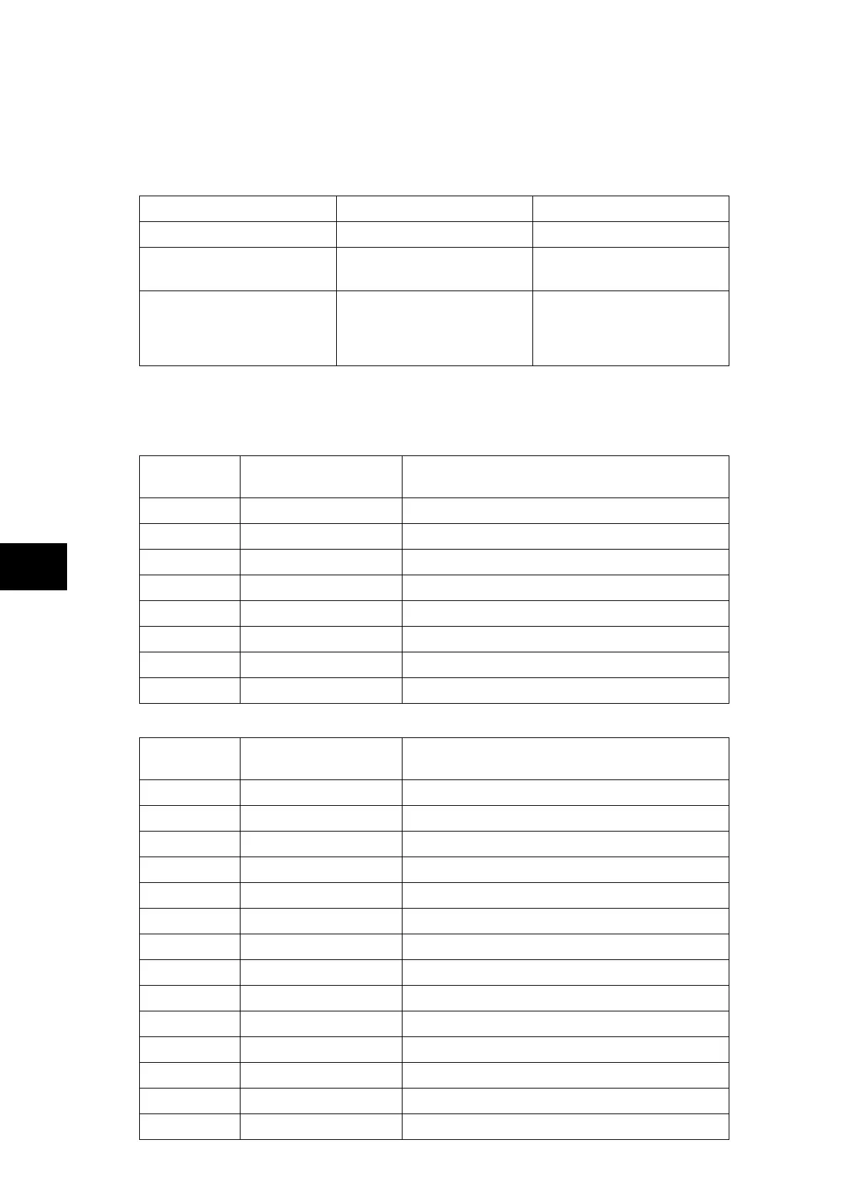
The P74x models are as follows:
Model Logic Inputs Relay Outputs
P741xxxAxxxxxxK 8 8
P742xxxAxxxxxxJ
P742xxxBxxxxxxJ
16
8
8
8 + 4 high break relays
P743xxxAxxxxxxK
P743xxxBxxxxxxK
P743xxxCxxxxxxK
P743xxxDxxxxxxK
24
16
24
16
16
16 + 4 high break relays
8 + 4 high break relays
8 + 8 high break relays
1.11 Logic input mapping
The default mappings for each of the opto-isolated inputs are as shown in the following table:
Central Unit P741:
Opto-Input
Number
P74x Relay Text Function
1 Input Label 01 Disable 87BB on zone 1 & zone 2
2 Input Label 02 Disable 87BB & 50BF on zone 1 & zone 2
3 Input Label 03 Disable 87BB & 50BF on zone 1
4 Input Label 04 Disable 87BB & 50BF on zone 2
5 Input Label 05 Maintenance mode authorization
6 Input Label 06 Not Mapped
7 Input Label 07 Not Mapped
8 Input Label 08 Block all protections (CU & PU)
Peripheral Unit P742:
Opto-Input
Number
P74x Relay Text Function
1 Input Label 01 Reset Indication
2 Input Label 02 Reset Trip Latch
3 Input Label 03 Isolator 1 closed auxiliary contact (89a)
4 Input Label 04 Isolator 1 open auxiliary contact (89b)
5 Input Label 05 Isolator 2 closed auxiliary contact (89a)
6 Input Label 06 Isolator 2 open auxiliary contact (89b)
7 Input Label 07 Circuit Breaker closed auxiliary contact (52a)
8 Input Label 08 Circuit Breaker open auxiliary contact (52b)
9 Input Label 09 Isolator 3 closed auxiliary contact (89a)
10 Input Label 10 Isolator 3 open auxiliary contact (89b)
11 Input Label 11 Mode 50BF disabled
12 Input Label 12 Can be linked to External 3 phase trip initiation
13 Input Label 13 CB not available
14 Input Label 14 Can be linked to External circuit breaker failure