P74x/EN OP/N
(OP) 5-
1.2 Busbar Protection
1.2.1 Bias Characteristic and Differential current setting
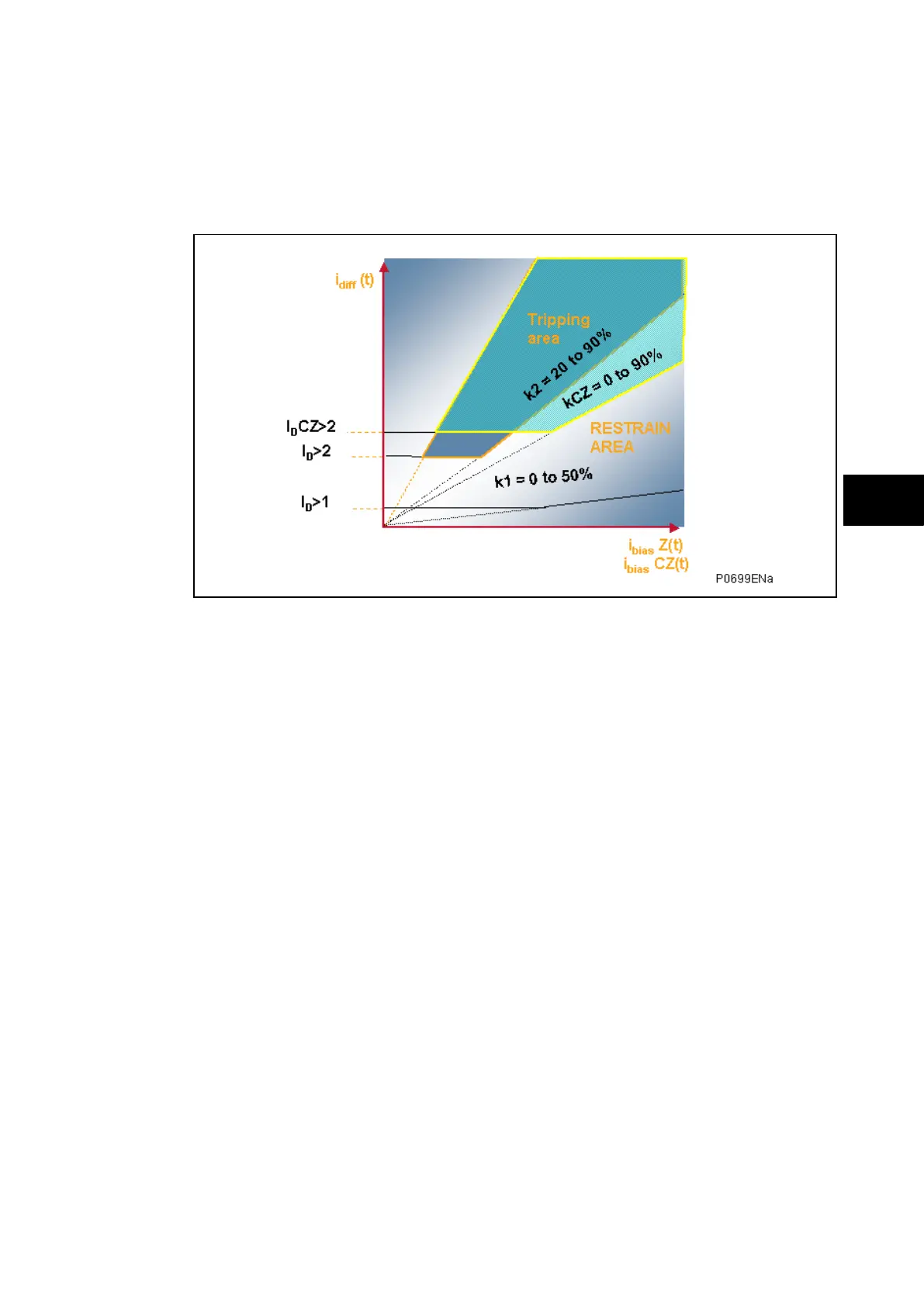
Figure 2 shows the characteristics of the P74x scheme phase differential element.
FIGURE 2: P74x SCHEME CHARACTERISTIC
The Phase characteristic is determined from the following protection settings:
• Area above the I
D
>2 High-set zone differential current threshold setting and the set
slope of the bias characteristic (k2 × I
bias
) (k2 is the percentage bias setting (“slope”)
for the zone)
Note: The origin of the bias characteristic slope is 0.
When an external fault condition causes CT saturation, a differential current is apparent and
is equal to the current of the saturated CT. The measured differential current may be
determined as an internal fault and initiate an unwanted trip of the bus bar. In order to avoid
a risk of tripping under these circumstances, P74x uses an ultra fast innovative algorithm
based on the prediction of the next samples and the calculation of the image of the flux of
the HV CT core. This signal-processing algorithm makes it possible to block a trip sample
within a window of 1,7 ms. A timer ‘Block Duration’ of 150 ms is used to block the differential
element in case of CT saturation detection.
1.2.2 Scheme supervision by "check zone” element
For security, the P74x scheme will only trip a particular busbar zone if that zone differential
element AND the check zone element are in agreement to trip.
The principal advantage of this element is total insensitivity to topological discrepancies.
Under such circumstances the "check zone" element will see two currents with equal
amplitude but of opposite sign in adjacent zones.
The Check Zone characteristic is determined from the following protection settings:
• Area above the I
D
CZ>2 High-set check zone differential current threshold setting and
the set slope of the bias characteristic (kCZ × I
bias
) (kCZ is the percentage bias
setting (“slope”) for the Check Zone)
Note: The origin of the bias characteristic slope is 0.