x/EN AP/Na7
-58 MiCOM P74
The above example shows a mesh corner arrangement. The scheme is split into four zones.
This configuration requires 1 central unit and 12 peripheral units.
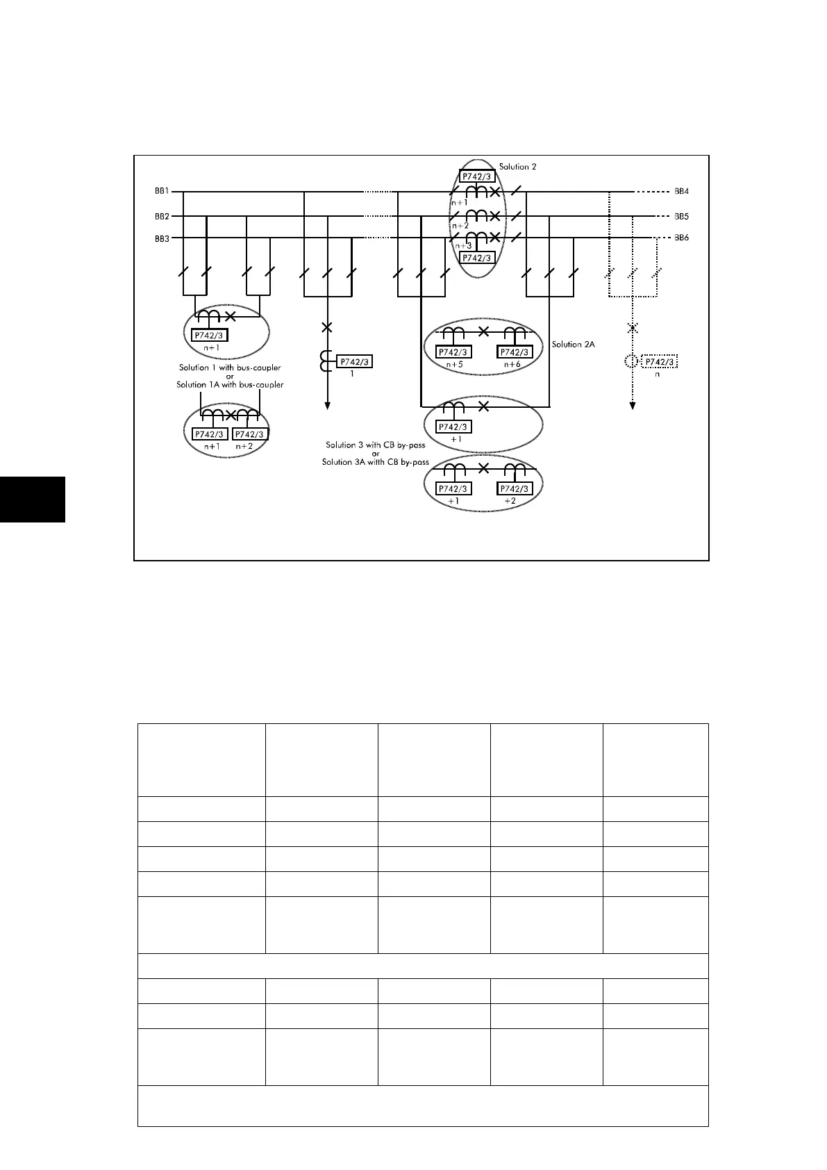
FIGURE 41: SIX MAIN BUS FOR S/S CB BUS-SECTIONS AND CB BY-PASS
The above example shows a six busbar arrangement with both a bus section and a bus
coupler. It is also possible to include bypass facilities. The scheme is split into six zones.
There are n feeders connected to the busbar. The bus coupler, bus section and bypass
circuit breakers can have either a single CT (solution 1, 2 and 3) on one side or CTs on both
sides (solution 1A, 2A and 3A).
This configuration requires 1 central unit and n plus the following number of peripheral units.
Solution Solution A
1 CT on BC
& 1 CT on
each BS
Solution B
2 CT on BC
& 2 CT on
each BS
Solution C
1 CT on BC
& 2 CT on
each BS
Solution D
2 CT on BC
& 1 CT on
each BS
Solution 1
Solution 1a
Solution 2
Solution 2a
Number of
peripheral units
required
n + 4 n + 8 n + 7 n + 5
If bypass facilities are to be included
Using solution 3
Using solution 3a
Number of
peripheral units
required
n + 5 n + 10 n + 8 n + 8
If a second bus coupler is added i.e. one bus coupler either side of the bus section and
no bypass facilities