CM
If a P991 test block is provided the connections should be checked against the scheme
(wiring) diagram. It is recommended that the supply connections are to the live side of the
test block [coloured orange with the odd numbered terminals (1, 3, 5, 7 etc.). The auxiliary
supply is normally routed via terminals 13 (supply positive) and 15 (supply negative), with
terminals 14 and 16 connected to the relay’s positive and negative auxiliary supply terminals
respectively. However, check the wiring against the schematic diagram for the installation to
ensure compliance with the customer’s normal practice.
4.1.5 Watchdog contacts
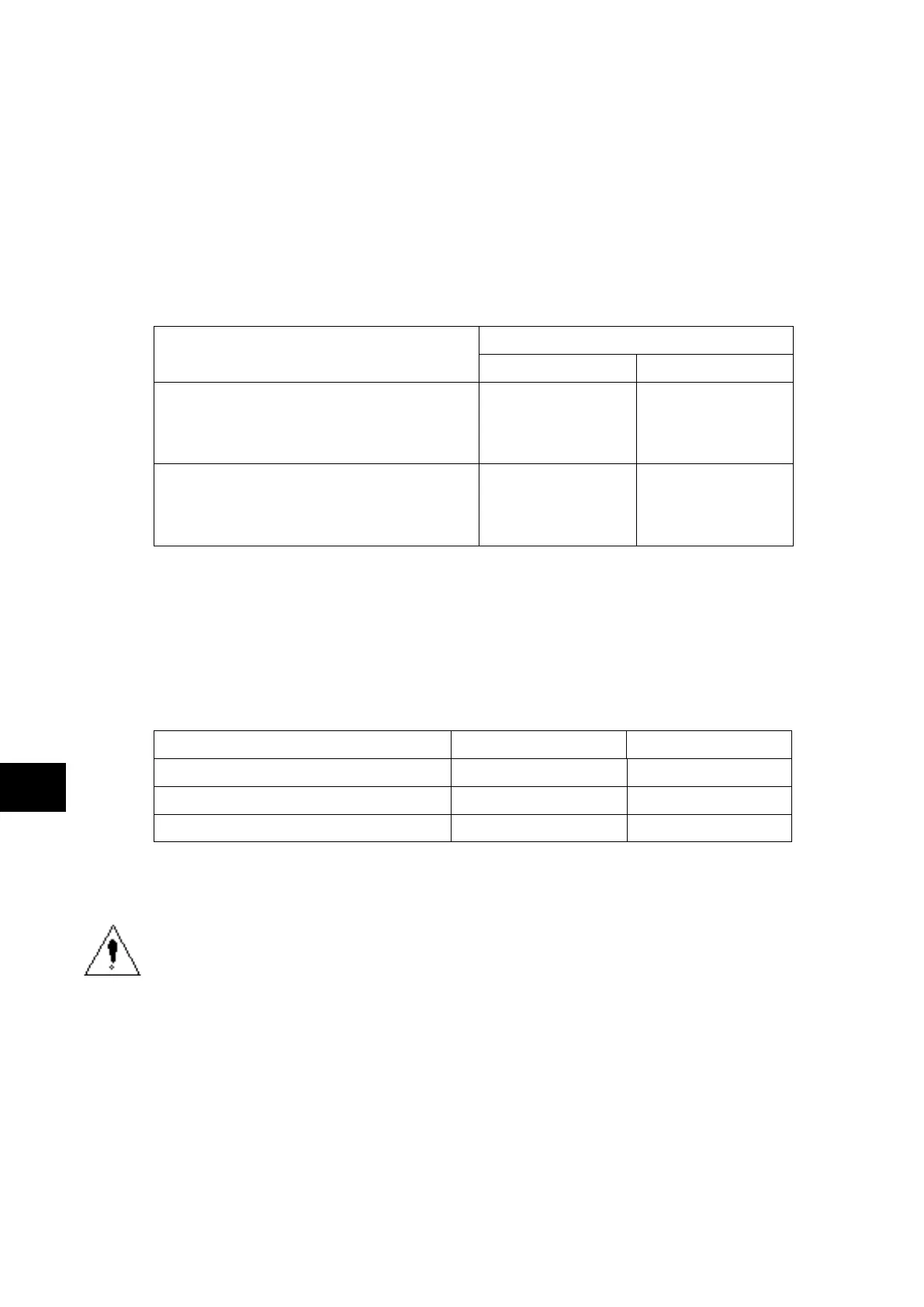
Using a continuity tester, check that the watchdog contacts are in the states given in Table 2
for a de-energised relay.
Terminals Contact state
Relay de-energised Relay energised
L11 – L12
E11 – E12
G11 – G12
(P741)
(P742)
(P743)
Closed Open
L13 – L14
E13 – E14
G13 – G14
(P741)
(P742)
(P743)
Open Closed
TABLE 2: WATCHDOG CONTACT STATUS
4.1.6 Auxiliary supply
The P74x relay can be operated from either a dc only or an ac/dc auxiliary supply depending
on the relay’s nominal supply rating. The incoming voltage must be within the operating
range specified in Table 3.
Without energising the relay measure the auxiliary supply to ensure it is within the operating
range.
Nominal supply rating DC [AC rms] DC operating range AC operating range
24 – 48V [–] 19 to 65V -
48 – 110V [30 – 100V] 37 to 150V 24 to 110V
110 – 250V [100 – 240V] 87 to 300V 80 to 265V
TABLE 3: OPERATIONAL RANGE OF AUXILIARY SUPPLY VX.
It should be noted that the P74x relay range can withstand an ac ripple of up to 12% of the
upper rated voltage on the dc auxiliary supply.
Do not energise the relay or interface unit using the battery charger with the battery
disconnected as this can irreparably damage the relay’s power supply circuitry.
Energise the relay only if the auxiliary supply is within the specified operating ranges. If a test
block is provided, it may be necessary to link across the front of the test plug to connect the
auxiliary supply to the relay.