x/EN ST/Na7
-
MiCOM P74
1.4 Disturbance recorder settings
The disturbance recorder settings include the record duration and trigger position, selection
of analog and digital signals to record, and the signal sources that trigger the recording.
The "DISTURBANCE RECORDER" menu columns are different for the Central Unit and the
Peripheral Units as shown in the configuration columns below.
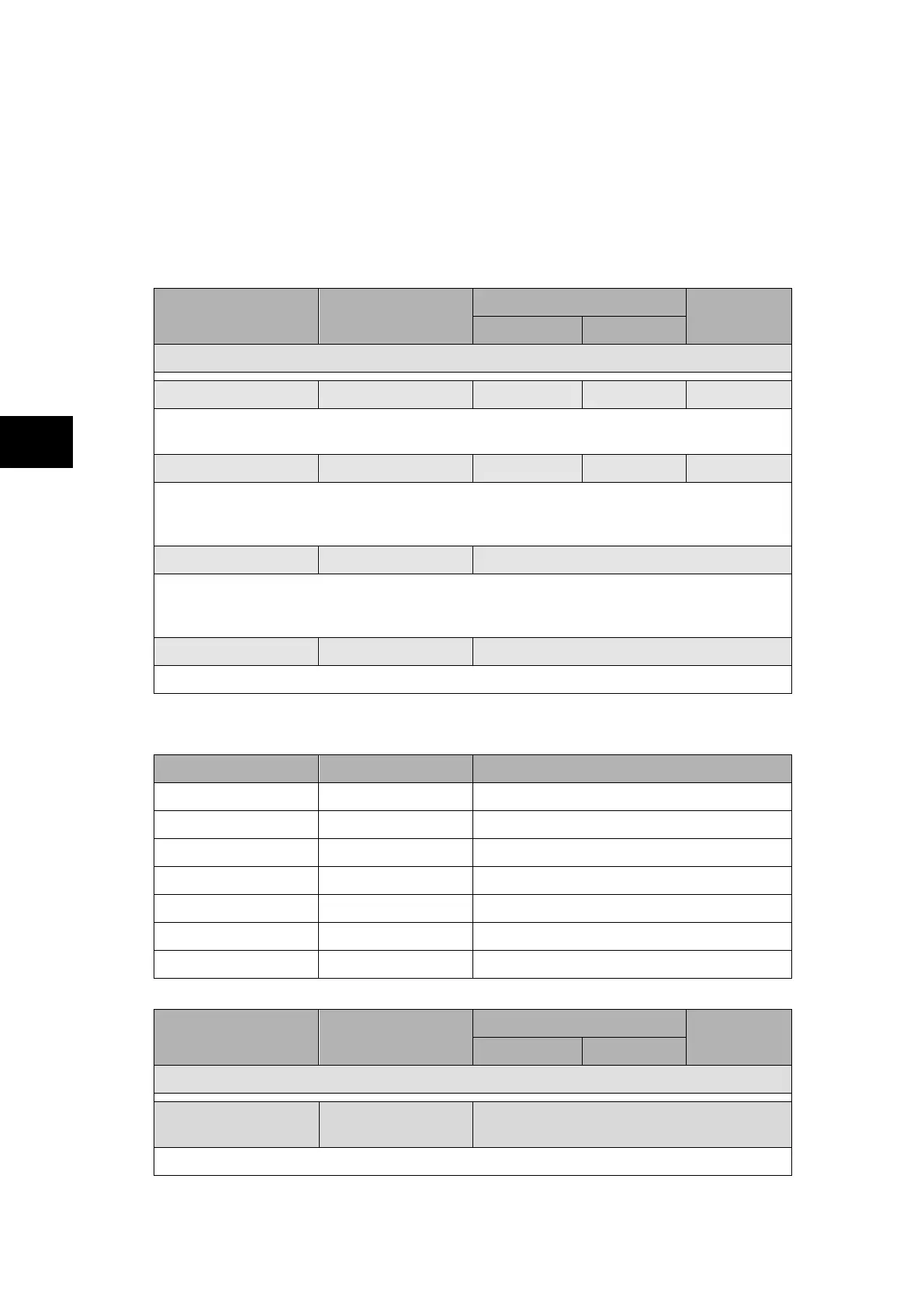
1.4.1 Central Unit P741
Menu Text Default Setting
Setting Range
Step Size
Min. Max.
DISTURB. RECORDER
Duration 1.2 s 1.2 s 1.2 s 0.0 s
This sets the overall recording time. The relay can typically store a minimum of 50 records,
each of 1.2 seconds duration in the CU (until the available memory is exhausted).
Trigger Position 33.3% 0.0% 100.0% 33.3%
This sets the trigger point as a percentage of the duration. For example, the default
settings show that the overall recording time is set to 1.2s with the trigger point being at
33.3% of this, giving 0.4 s pre-fault and 0.8 s post fault recording times.
Trigger Mode Single Single / extended
If set to single mode, if a further trigger occurs whilst a recording is taking place, the
recorder will ignore the trigger. However, if this has been set to "Extended", the post
trigger timer will be reset to zero, thereby extending the recording time.
Analog. Channel 1 I
A
diff Non settable
The Phase A differential calculated current is assigned to this channel.
The following lines give the default settings for analog channels 2 to 8.
Menu Text Default Setting Explanation
Analog. Channel 2 I
B
diff Phase B differential calculated current
Analog. Channel 3 I
C
diff Phase C differential calculated current
Analog. Channel 4 I
N
diff Neutral differential calculated current
Analog. Channel 5 I
A
bias Phase A bias calculated current
Analog. Channel 6 I
B
bias Phase B bias calculated current
Analog. Channel 7 I
C
bias Phase C bias calculated current
Analog. Channel 8 I
N
bias Neutral bias calculated current
Menu Text Default Setting
Setting Range
Step Size
Min. Max.
DISTURB. RECORDER
Digital Input 1 Circt Flt Lck z1
Any O/P Contacts or Any Opto Inputs or
Internal Digital Signals
The Circuitry fault blocks zone 1 digital channel is assigned to this channel.