CM
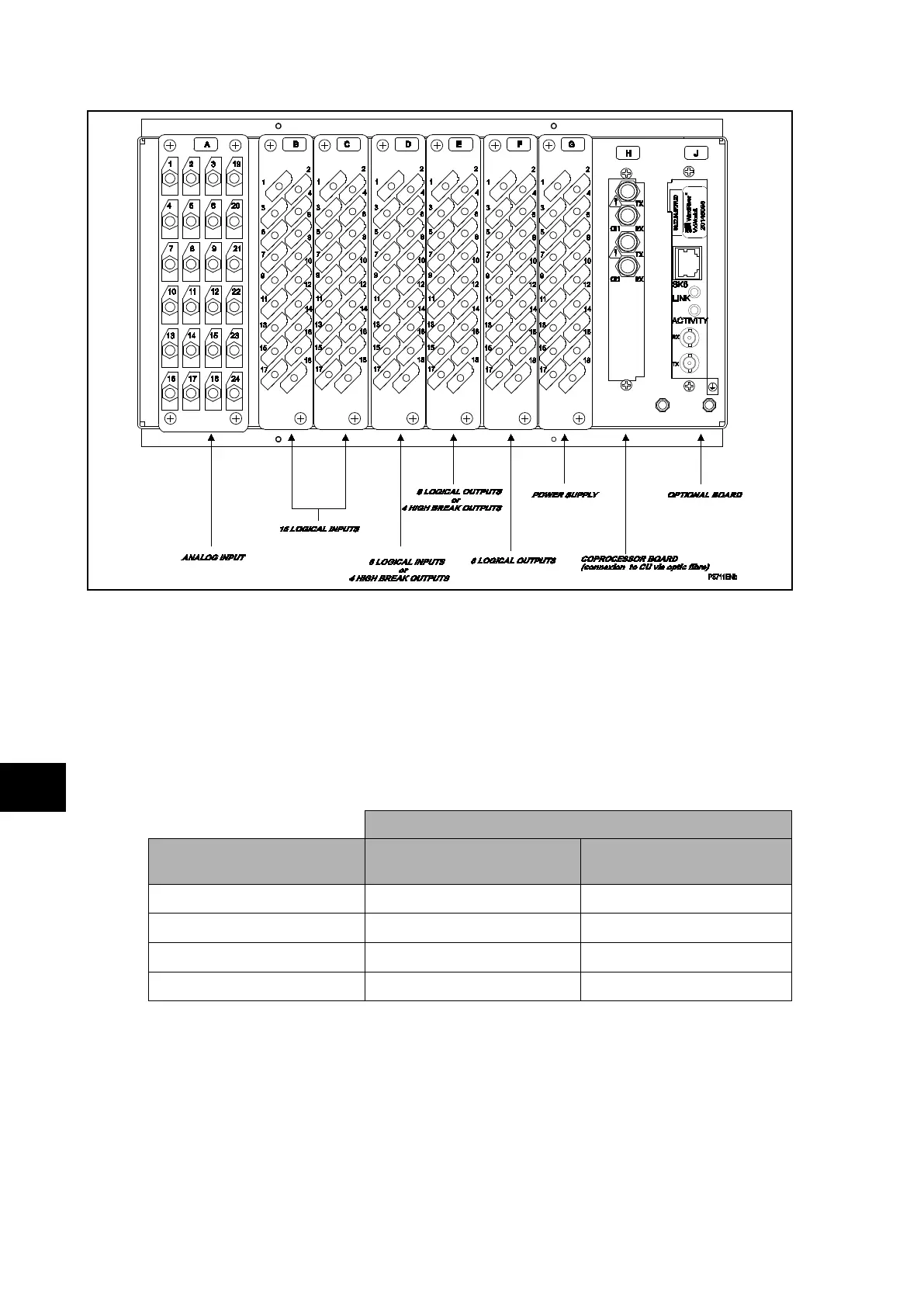
FIGURE 2: REAR TERMINAL BLOCKS ON P743
The heavy duty terminal block is fastened to the rear panel using four crosshead screws.
These are located top and bottom between the first and second, and third and fourth,
columns of terminals (see Figure 3).
Note: The use of a magnetic bladed screwdriver is recommended to
minimise the risk of the screws being left in the terminal block or lost.
Pull the terminal block away from the rear of the case and check with a continuity tester that
all the shorting switches being used are closed. Table 1 shows the terminals between which
shorting contacts are fitted.
Shorting contact between terminals
Current input
P742
1A – common – 5A
P743
1A – common – 5A
Ι
A
B3 – B2 – B1 A3 – A2 – A1
Ι
B
B6 – B5 – B4 A6 – A5 – A4
Ι
C
B9 – B8 – B7 A9 – A8 – A7
Ι
N
B12 – B11 – B10 A12 – A11 – A10
TABLE 1: CURRENT TRANSFORMER SHORTING CONTACT LOCATIONS