pplication Notes
P74x/EN AP/N
1, P742, P743 (AP) 6-
The number of additional peripheral units being dependant on the number of bus section/bus
coupler CTs. The type of peripheral unit used for each bay will depend on the i/o
requirements of the bay in question.
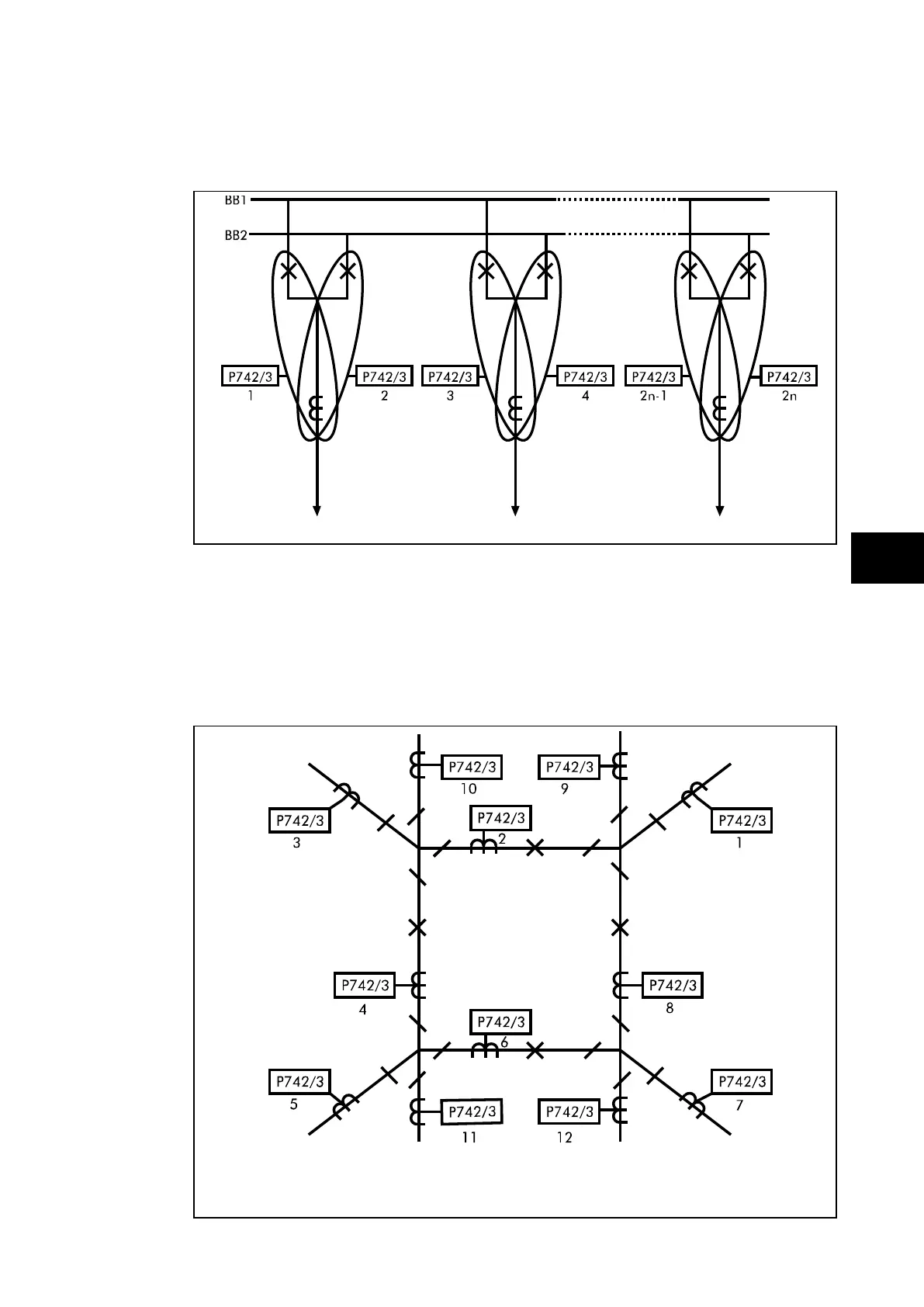
FIGURE 39: DOUBLE BUS BAR WITH TWO CIRCUIT BREAKERS PER FEEDER
The above example shows a double busbar with two circuit breakers on each feeder. The
scheme is split into two zones. There are n feeders connected to the busbar.
This configuration should require 1 central unit and 2 x n peripheral units but only n
Peripheral Units can be used. In each bay the two peripheral units should share the CT, and
each circuit breaker should be assigned to a separate peripheral unit but when one
Peripheral Unit is used per feeder, the trip order is connected to the two breakers.
FIGURE 40: MESH CORNER