x/EN AP/Na7
-60 MiCOM P74
9. APPLICATION OF NON PROTECTION FUNCTIONS
The non-protection features for the scheme are summarised below:
• Scheme can be centralised/distributed – if space is not available to locate the busbar
protection centrally it is possible to decentralise the scheme and locate the units within
other protection cubicles
• Local, zone and scheme measurements – various measurements are available locally
via the relay LCD or remotely via the serial communication link
• Event, fault and disturbance recording – Comprehensive post fault analysis available via
event lists, disturbance records and fault records which can be accessed locally via the
relay LCD or remotely via the serial communication link (PU -> CU)
• Real time clock/time synchronisation – Time synchronisation available via IRIG-B input
(option in Central Unit that synchronises the PUs)
• Four settings groups – Independent remotely selectable setting groups to allow for
customer specific applications
• CB and isolator state monitoring – indication of the circuit breaker/isolator position via
the auxiliary contacts, scheme acts accordingly should discrepancy conditions be
detected
• CB control – available locally via the HMI
• Commissioning test facilities
• Continuous self monitoring – extensive self checking routines to ensure maximum
reliability
• Communications supervision – detects communication failure between units and enables
remedial action to be taken e.g. switch to communication independent backup protection
locally and disregard feeder at a zone level
• Graphical programmable scheme logic – allowing user defined protection and control
logic to be tailored to the specific application
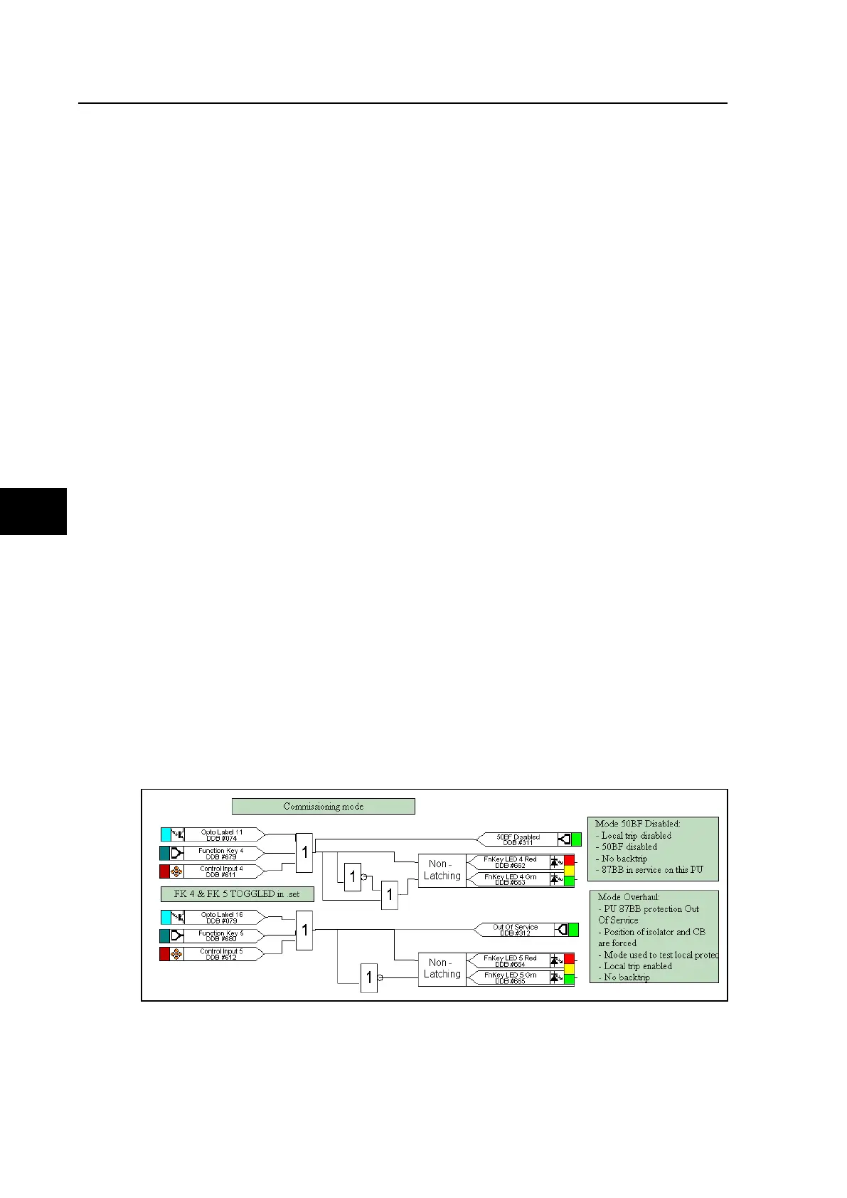
9.1 Function keys
The following default PSL logic illustrates the programming of function keys to enable/disable
the commissioning mode functionality.
FIGURE 42: COMMISSIONING MODE DEFAULT PSL
Note: Energizing two inputs to an LED conditioner creates a YELLOW
illumination.