x/EN AP/Na7
-24 MiCOM P74
4.2.5 TCS scheme 3
4.2.5.1 Scheme description
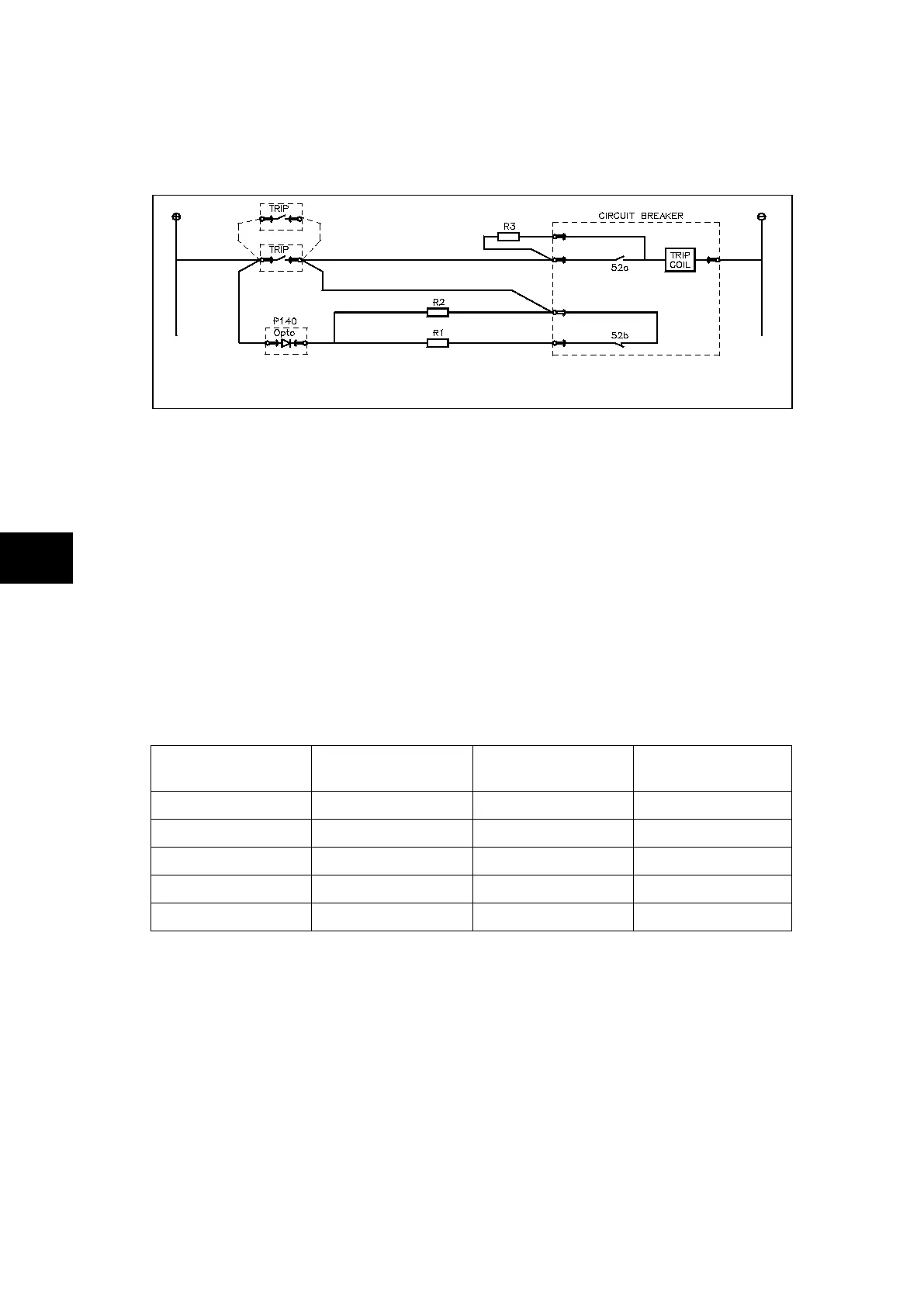
FIGURE 6: TCS SCHEME 3
Scheme 3 is designed to provide supervision of the trip coil with the breaker open or closed,
but unlike schemes 1 and 2, it also provides pre-closing supervision. Since only one opto
input is used, this scheme is not compatible with latched trip contacts. If circuit breaker
status monitoring is required a further 1 or 2 opto inputs must be used.
When the breaker is closed, supervision current passes through the opto input, resistor R2
and the trip coil. When the breaker is open current flows through the opto input, resistors R1
and R2 (in parallel), resistor R3 and the trip coil. Unlike schemes 1 and 2, supervision
current is maintained through the trip path with the breaker in either state, thus giving
pre-closing supervision.
As with schemes 1 and 2, resistors R1 and R2 are used to prevent false tripping, if the
opto-input is accidentally shorted. However, unlike the other two schemes, this scheme is
dependent upon the position and value of these resistors. Removing them would result in
incomplete trip circuit monitoring. The table below shows the resistor values and voltage
settings required for satisfactory operation.
Auxiliary Voltage
(Vx)
Resistor R1 & R2
(ohms)
Resistor R3 (ohms)
Opto Voltage
Setting
24/27 - - -
30/34 - - -
48/54 1.2k 0.6k 24/27
110/250 2.5k 1.2k 48/54
220/250 5.0k 2.5k 110/125
Note: Scheme 3 is not compatible with auxiliary supply voltages of 30/34
volts and below.
TABLE 2:
SCHEME 3 OPTIONAL R1, R2 & R3 OPTO INPUT RESISTOR VALUES
4.2.6 Scheme 3 PSL
The PSL for scheme 3 is identical to that of scheme 1 (see figure 3).