x/EN AP/Na7
-48 MiCOM P74
8. STANDARD CONFIGURATIONS
The following information relates only to the more common standard schemes. For further
information on the accommodation of other busbar configurations consult your GE
representative.
The main rule to calculate the minimum number of Peripheral Unit to use is:
1 Peripheral Unit per CT.
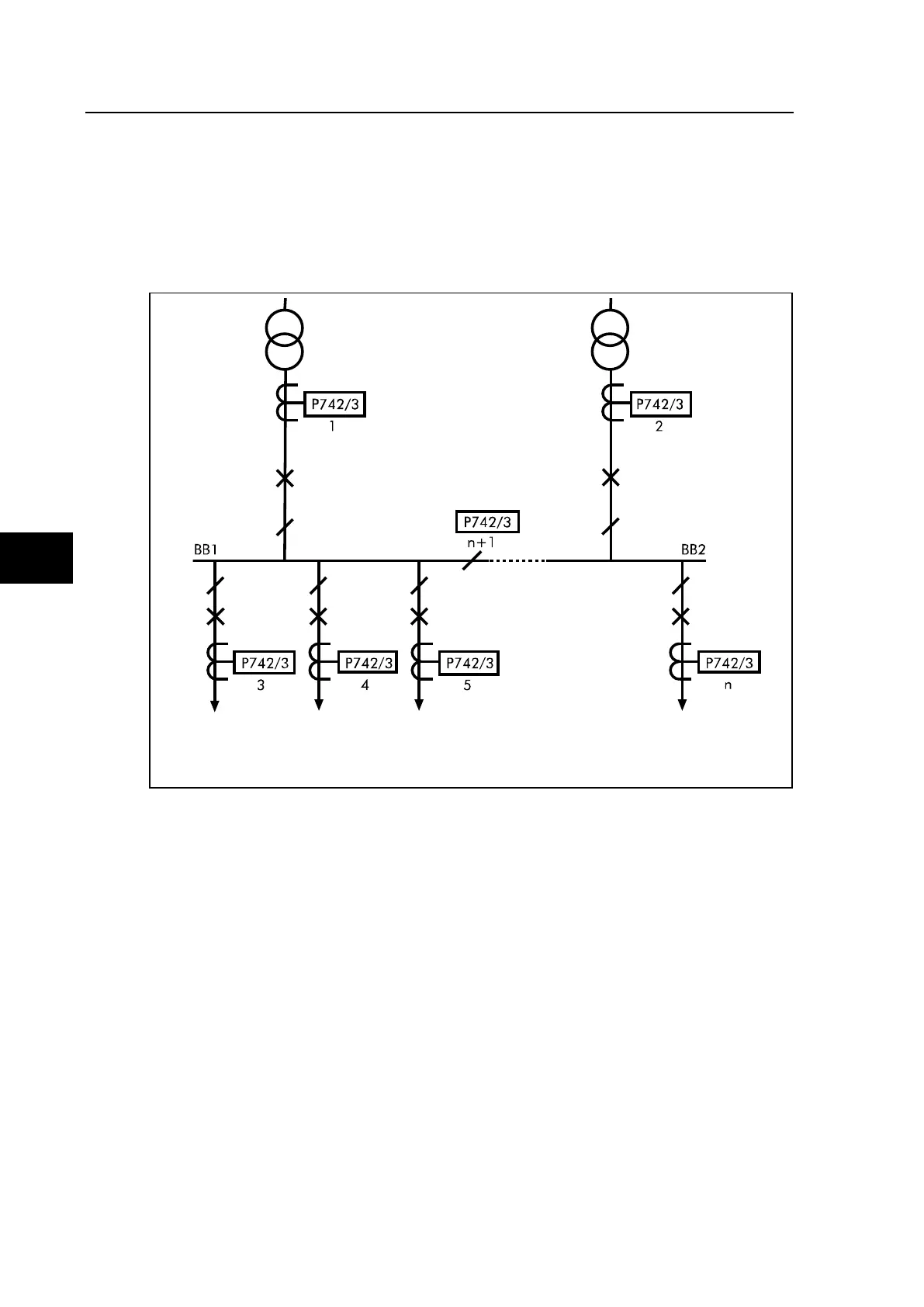
FIGURE 29: SINGLE BUSBAR APPLICATION WITH BUS SECTION ISOLATOR
The above example shows a single busbar with a bus section isolator. It is split into two
zones. There are n feeders connected to the busbar. This configuration requires 1 central
unit and n peripheral units (the additional peripheral unit being for the bus section isolator is
optional). The type of peripheral unit used for each bay will depend on the i/o requirements
of the bay in question.