CM
4.1.1 Visual inspection
Carefully examine the relay to see that no physical damage has occurred since installation.
The rating information given under the top access cover on the front of the relay should be
checked to ensure it is correct for the particular installation.
Ensure that the case earthing connections, bottom left-hand corner at the rear of the relay
case, are used to connect the relay to a local earth bar using an adequate conductor.
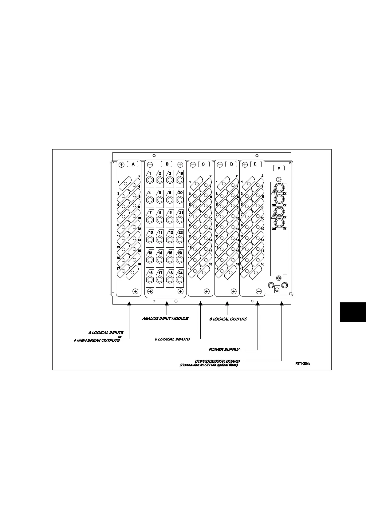
4.1.2 Current transformer shorting contacts
If required, the current transformer shorting contacts can be checked to ensure that they
close when the heavy duty terminal block (block reference B for P742 and A for P743 in
Figure 1 and Figure 2) is disconnected from the current input PCB.
FIGURE 1: REAR TERMINAL BLOCKS ON P742