CM
4.2.4 Field voltage supply
The relay generates a field voltage of nominally 48V dc that can be used to energise the
opto-isolated inputs (alternatively the substation battery may be used).
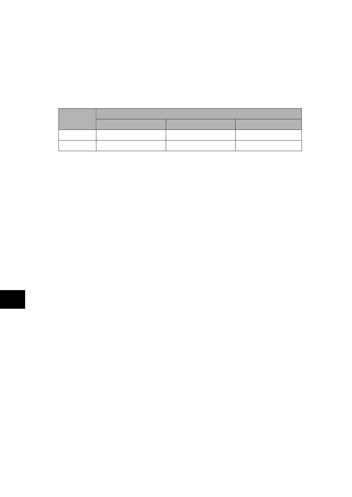
Measure the field voltage across the terminals 7 and 9 on the terminal block given in Table
4. Check that the field voltage is within the range 40V to 60V when no load is connected and
that the polarity is correct.
Repeat for terminals 8 and 10.
Supply rail
Terminals
P741 P742 P743
+ve L7 & L8 E7 & E8 G7 & G8
–ve L9 & L10 E9 & E10 G9 & G10
TABLE 4: FIELD VOLTAGE TERMINALS
4.2.5 Input opto-isolators
This test checks that all the opto-isolated inputs on the relay are functioning correctly. The
P741 relay has 8 opto-isolated inputs while the P742 relay has 16 opto-isolated inputs and
P743 relays has 24 opto-isolated inputs.
The opto-isolated inputs should be energised one at a time, see the external connection
diagrams for the terminal numbers. Ensuring correct polarity, connect the field supply voltage
to the appropriate terminals for the input being tested.
Note: The opto-isolated inputs may be energised from an external dc
auxiliary supply (e.g. the station battery) in some installations. Check
that this is not the case before connecting the field voltage otherwise
damage to the relay may result.
The status of each opto-isolated input can be viewed using either cell [SYSTEM DATA,
Opto I/P Status] or [COMMISSION TESTS, Opto I/P Status], a ‘1’ indicating an energised
input and a ‘0’ indicating a de-energised input. When each opto-isolated input is energised
one of the characters on the bottom line of the display will change to indicate the new state
of the inputs.
4.2.6 Output relays
This test checks that all the output relays are functioning correctly. The P741 and P742
relays have 8 output relays while P743 relay has 16 output relays.
See the external Connection Diagrams for the terminal numbers.
Ensure that the relay is still in test mode by viewing cell [COMMISSION TESTS, Test Mode]
to ensure that it is set to ‘Blocked’.
The output relays should be energised one at a time. To select output relay 1 for testing, set
cell [COMMISSION TESTS, Test Pattern] as appropriate.
Connect a continuity tester across the terminals corresponding to output relay 1 as shown in
external connection diagram.
To operate the output relay set cell COMMISSION TESTS, Contact Test] to ‘Apply Test’.
Operation will be confirmed by the continuity tester operating for a normally open contact
and ceasing to operate for a normally closed contact. Measure the resistance of the contacts
in the closed state.
Reset the output relay by setting cell [COMMISSION TESTS, Contact Test] to ‘Remove
Test’.