x/EN PL/Na7
7-
MiCOM P74
1.6.17 Gate properties
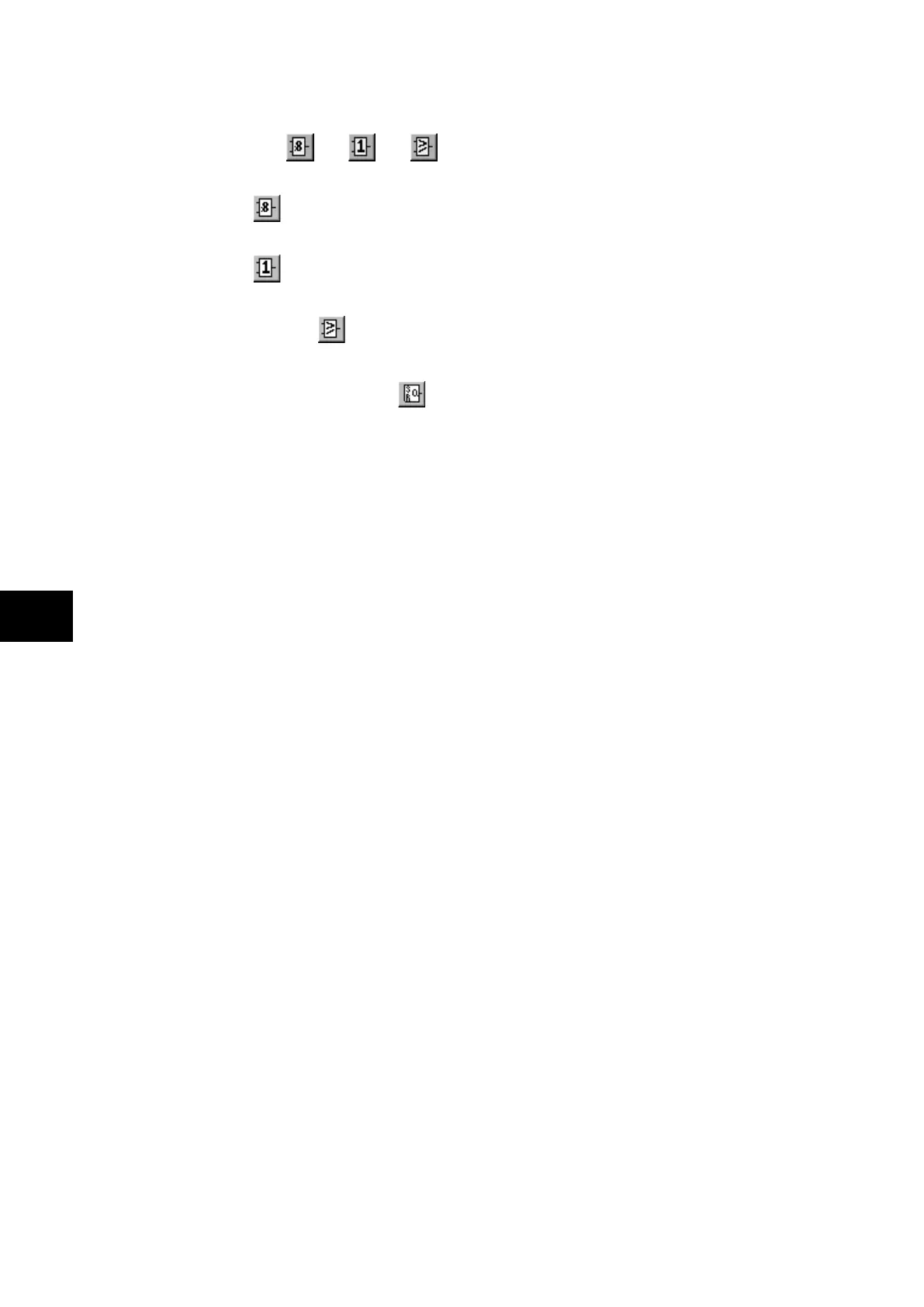
A Gate may be an AND, OR, programmable gate or SR Latch .
An AND gate requires that all inputs are TRUE for the output to be TRUE.
An OR gate
requires that one or more input is TRUE for the output to be TRUE.
A Programmable gate
requires that the number of inputs that are TRUE is equal to or
greater than its ‘Inputs to Trigger’ setting for the output to be TRUE.
Three variants of the SR latch gate
are available. They are:
• Standard – no input dominant
• Set Input Dominant
• Reset Input Dominant
The output of the gate, Q is latched, i.e. its state is non-volatile upon power cycle.
The inversions of the input and output signals are supported.
The state of Q is reset when a new PSL is downloaded to the relay or when the active
setting group is changed. The maximum number of SR Latch gates is 64.
The evaluation of the Q state is carried out after all the DDB changes have completed, i.e. at
the end of the protection cycle and synchronised with protection task. Hence there is an
inherent delay of a protection cycle in processing every one of the SR gates and the delay
increases if the SR gates are connected one after another.
The user has to be aware that if there is a timer before the SR gate, then an additional delay
of a protection cycle will be incurred before the Q state is changed.
The logic operations of the three variants of the gate are depicted in the diagram below:-