P74x/EN OP/N
(OP) 5-
5.6 Setting groups selection
The setting groups can be changed either via opto inputs, via a menu selection, via the
hotkey menu or via function keys. In the Configuration column if 'Setting Group - select via
optos' is selected then any opto input or function key can be programmed in PSL to select
the setting group as shown in the table below. If 'Setting Group - select via menu' is selected
then in the Configuration column the 'Active Settings - Group1/2/3/4' can be used to select
the setting group.
The setting group can be changed via the hotkey menu providing ‘Setting Group select via
menu’ is chosen.
5.7 Control inputs
The control inputs function as software switches that can be set or reset either locally or
remotely. These inputs can be used to trigger any function that they are connected to as part
of the PSL. There are three setting columns associated with the control inputs that are:
“CONTROL INPUTS”, “CTRL. I/P CONFIG.” and “CTRL. I/P LABELS”. The function of these
columns is described below:
Menu Text Default Setting Setting Range Step Size
CONTROL INPUTS
Ctrl I/P Status 00000000000000000000000000000000
Control Input 1 No Operation No Operation, Set, Reset
Control Input 2 to 32 No Operation No Operation, Set, Reset
The Control Input commands can be found in the ‘Control Input’ menu. In the ‘Ctrl. Ι/P status’
menu cell there is a 32 bit word which represent the 32 control input commands. The status
of the 32 control inputs can be read from this 32-bit word. The 32 control inputs can also be
set and reset from this cell by setting a 1 to set or 0 to reset a particular control input.
Alternatively, each of the 32 Control Inputs can be set and reset using the individual menu
setting cells ‘Control Input 1, 2, 3’ etc. The Control Inputs are available through the relay
menu as described above and also via the rear communications.
In the programmable scheme logic editor 32 Control Input signals, DDB 800 – 831, which
can be set to a logic 1 or On state, as described above, are available to perform control
functions defined by the user.
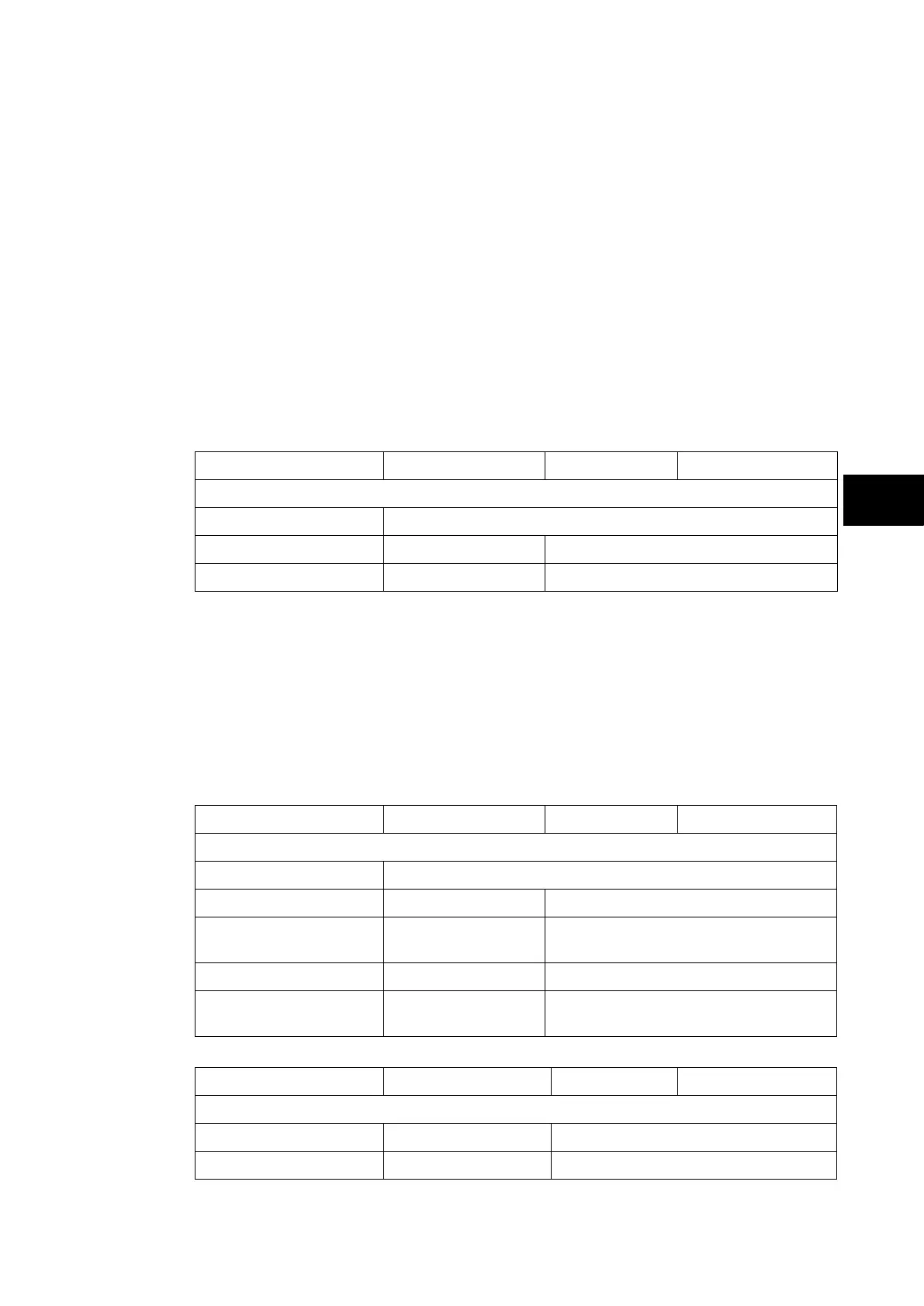
Menu Text Default Setting Setting Range Step Size
CTRL. I/P CONFIG.
Hotkey Enabled 11111111111111111111111111111111
Control Input 1 Latched Latched, Pulsed
Ctrl Command 1 SET/RESET
SET/RESET, IN/OUT,
ENABLED/DISABLED, ON/OFF
Control Input 2 to 32 Latched Latched, Pulsed
Ctrl Command 2 to 32 SET/RESET
SET/RESET, IN/OUT,
ENABLED/DISABLED, ON/OFF
Menu Text Default Setting Setting Range Step Size
CTRL. I/P LABELS
Control Input 1 Control Input 1 16 character text
Control Input 2 to 32 Control Input 2 to 32 16 character text