pplication Notes
P74x/EN AP/N
1, P742, P743 (AP) 6-
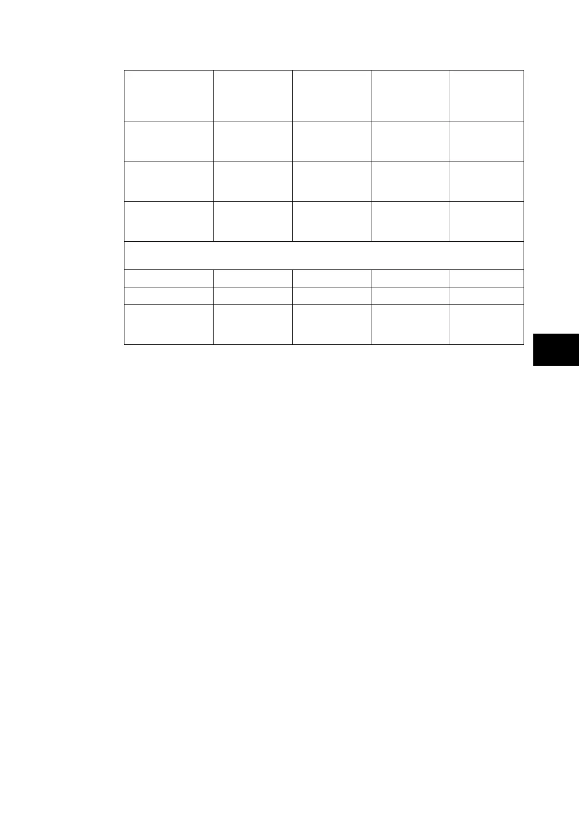
Solution Solution A
1 CT on BC
& 1 CT on
each BS
Solution B
2 CT on BC
& 2 CT on
each BS
Solution C
1 CT on BC
& 2 CT on
each BS
Solution D
2 CT on BC
& 1 CT on
each BS
Using solution 1
for the 2
nd
coupler
Using solution 1a
for the 2
nd
coupler
Number of
peripheral units
required
n + 5 n + 10 n + 8 n + 7
If a second bus coupler is added i.e. one bus coupler either side of the bus section and
bypass facilities are included
Using solution 3
Using solution 3a
Number of
peripheral units
required
n + 6 n + 12 n + 9 n + 10
TABLE 7: NUMBER OF REQUIRED PU’S FOR FIGURE 41
The number of additional peripheral units being dependant on the number of bus section/bus
coupler CTs. The type of peripheral unit used for each bay will depend on the i/o
requirements of the bay in question.