x/EN MT/Ma7
-
MiCOM P74
P3011ENa
SERIAL No.
ZN0001
D
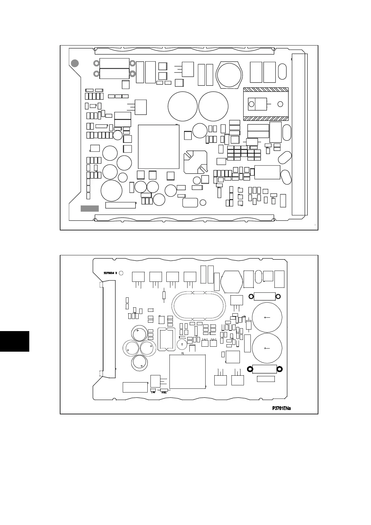
FIGURE 9: TYPICAL POWER SUPPLY BOARD FOR P742 & P743
FIGURE 10: ADDITIVE POWER SUPPLY BOARD FOR P741
Slot the power supply module back into the relay case, ensuring that it is pushed fully back
on to the rear terminal blocks.
Refit the front panel using the reverse procedure to that given in section. After refitting and
closing the access covers on size 60TE/80TE cases, press at the location of the
hinge-assistance T-pieces so that they click back into the front panel moulding.
Once the relay has been reassembled after repair, it should be recommissioned in
accordance with the instructions in sections 1 to 8 inclusive of the commissioning and
maintenance section P74x/EN CM.