x/EN AP/Na7
-52 MiCOM P74
Solution Solution A
& 1 CT on BS
Solution B
& 2 CT on BS
Solution C
& 2 CT on BS
Solution D
& 1 CT on BS
Using solution 1a
for the 2
nd
coupler
Number of
peripheral units
required
n + 3 n + 6 n + 4 n + 5
TABLE 3: NUMBER OF REQUIRED PU’S FOR FIGURE 33
The additional peripheral unit being for the bus section isolator is optional.
The number of additional peripheral units being dependant on the number of bus section/bus
coupler CTs. The type of peripheral unit used for each bay will depend on the i/o
requirements of the bay in question.
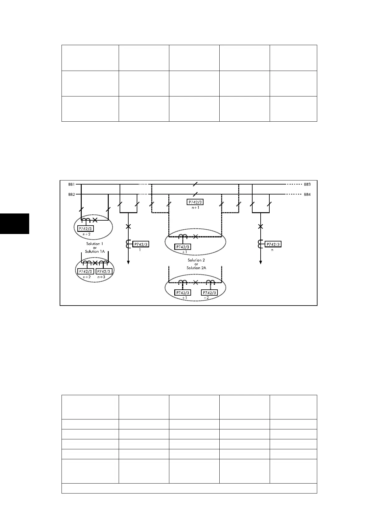
FIGURE 34: DOUBLE BUSBAR APPLICATION
WITH BUS COUPLER AND BUS SECTION
WITH ADDITIONAL BUS SECTION ISOLATORS
The above example shows a double busbar with both a bus section and a bus coupler. The
bus section also has additional bus section isolators and allows for bus section bypass. The
scheme is split into four zones. There are n feeders connected to the busbar. The bus
coupler and bus section circuit breakers can have either a single CT (solution 1 and 2) on
one side or CTs on both sides (solution 1a or 2a). This configuration requires 1 central unit
and n plus the following number of peripheral units. The total number of peripheral units
required allow for a peripheral unit for the bus section isolators.
Solution Solution A
1 CT on BC
& 1 CT on BS
Solution B
2 CT on BC
& 2 CT on BS
Solution C
1 CT on BC
& 2 CT on BS
Solution D
2 CT on BC
& 1 CT on BS
Solution 1
Solution 1a
Solution 2
Solution 2a
Number of
peripheral units
required
n + 2 n + 4 n + 3 n + 3
If a second bus coupler is added i.e. one bus coupler either side of the bus section