53
────────────────────────────────────────────────────
5.3 Interfaces
────────────────────────────────────────────────────
WARNING
To avoid electrocution, turn off the power to all devices before
pluggingor unplugging any of the interface connectors.
CAUTION
To avoid damage to the product, do not short-circuit the output terminal
and do not input voltage to the output terminal.
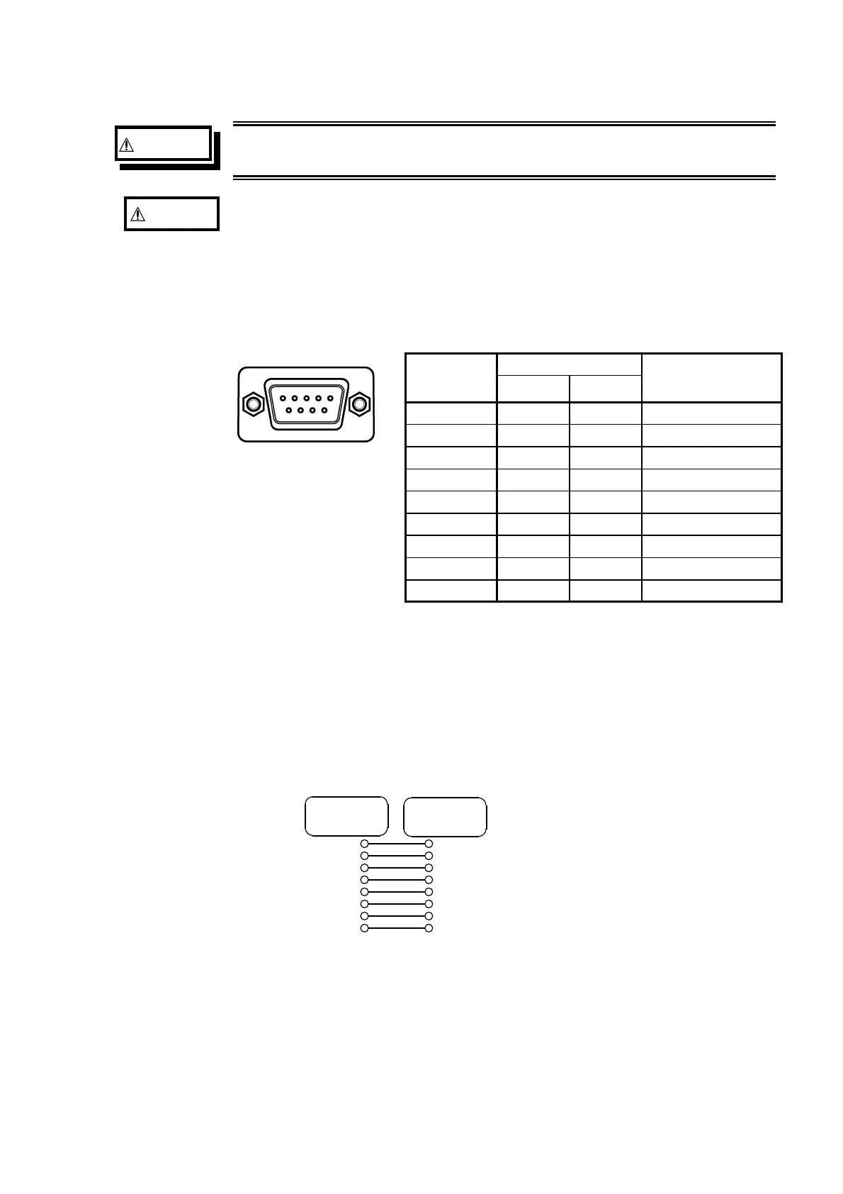
Unit side
67 8 9
12345
Connector
(Dsub)
Pin number
Signals
Function
RS-232C CCITT
1 Unused
2 BB(RxD) 104 Reception data
3 BA(TxD) 103 Transmission data
4 CD(DTR) 108/2 Data terminal ready
5 AB(GND) 102 Signal ground
6 Unused
7 CA(RTS) 105 Ready to send
8 CB(CTS) 106 Clear to send
9 Unused
Cable
2
6
3
4
5
7
8
SHELL
3
2
6
5
8
7
SHELL
4
D-sub
9pin female
D-sub
9pin female
Connecting to the Personal Computer
Connect the RS-232C connector on the unit to the serial port on the PC with
an RS-232C cable. The RS-232C connector on the 7075 is configured as a
data terminal (DTE) device.
(1) Required cable wiring
Connection lines: reverse type (straight-through wiring)
Cable wiring is as shown.
(2) Connection with PC/AT compatible computers.