64
────────────────────────────────────────────────────
7.3 Description of Sync hronized Operation
────────────────────────────────────────────────────
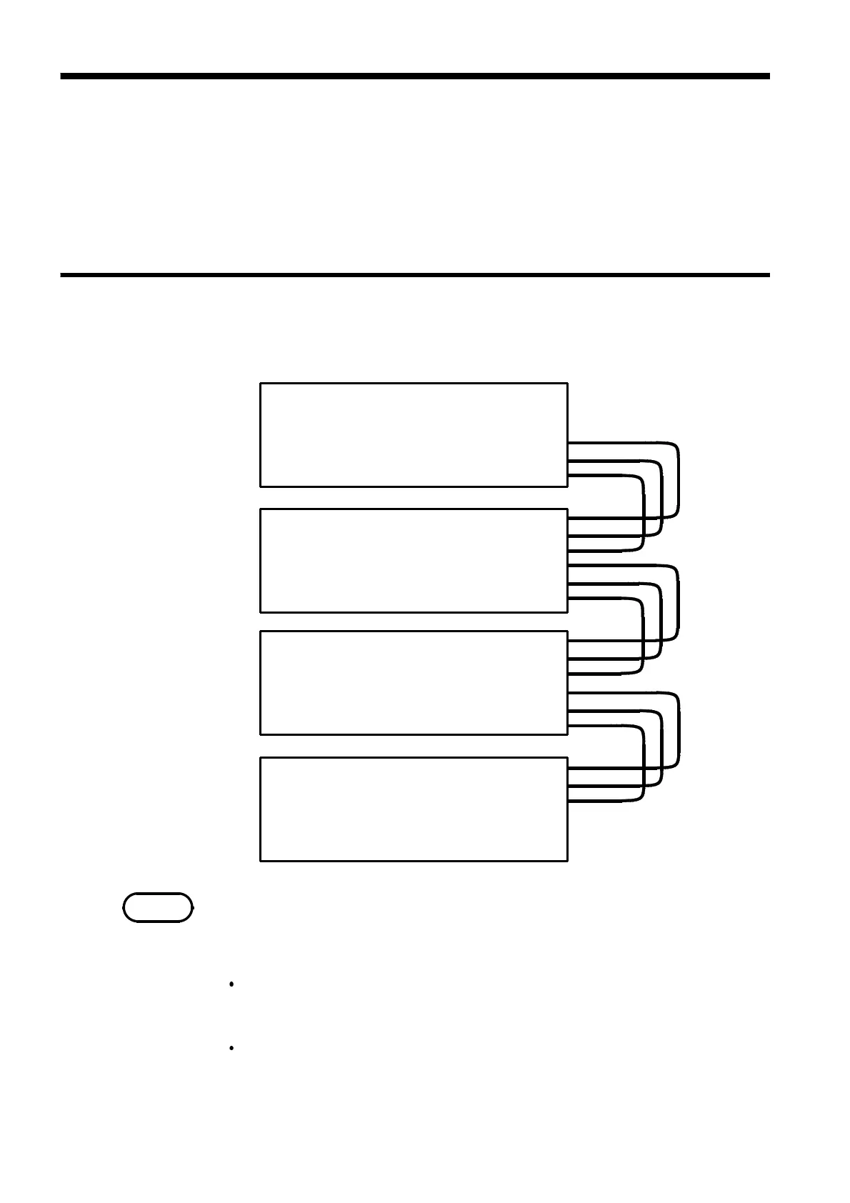
7.3.1 Connection
MASTER CLK IN
SYNC CLK IN
RUN/STOP IN
MASTER CLK OUT
SYNC CLK OUT
RUN/STOP OUT
MASTER CLK IN
SYNC CLK IN
RUN/STOP IN
MASTER CLK OUT
SYNC CLK OUT
RUN/STOP OUT
MASTER CLK IN
SYNC CLK IN
RUN/STOP IN
MASTER CLK OUT
SYNC CLK OUT
RUN/STOP OUT
MASTER CLK IN
SYNC CLK IN
RUN/STOP IN
MASTER CLK OUT
SYNC CLK OUT
RUN/STOP OUT
Master
Slave 1
Slave 2
Slave 3
NOTE
7.3 Description of Synchronized Operation
Up to four units can be connected via their external control terminals to
operate synchronously (as a master and three slaves). For synchronized
operation, the 7075s are connected in cascade so that all slaves are governed
by the following control signals from the master unit: RUN/STOP, MASTER
CLK and SYNC CLK.
One master unit and up to three slave units can be used in synchronized
drive. The control signal connections are shown here.
Never turn on any slave unit before turning on the master unit. If this
occurs, the slave unit may not output the proper waveforms.
With the connections above, if the system stops at a setting made according
to "3.7.17 Setting the Total Number of Loops," the following events occur:
When the master unit is stopped:
All slave units stop. (For the offset value, the last data continues to be
output.)
When a slave unit is stopped:
Only the involved slave unit stops. No other units are affected. The
RUN/STOP key on the stopped slave unit remains lit until the master unit
stops. (For the offset value, the last data continues to be output.)