65
────────────────────────────────────────────────────
7.3 Description of Sync hronized Operation
────────────────────────────────────────────────────
7.3.2 Connecting the Cables
CAUTION
The input logic level is 0 to 5 V. To avoid damage to the product, do not
apply voltage other than this level.
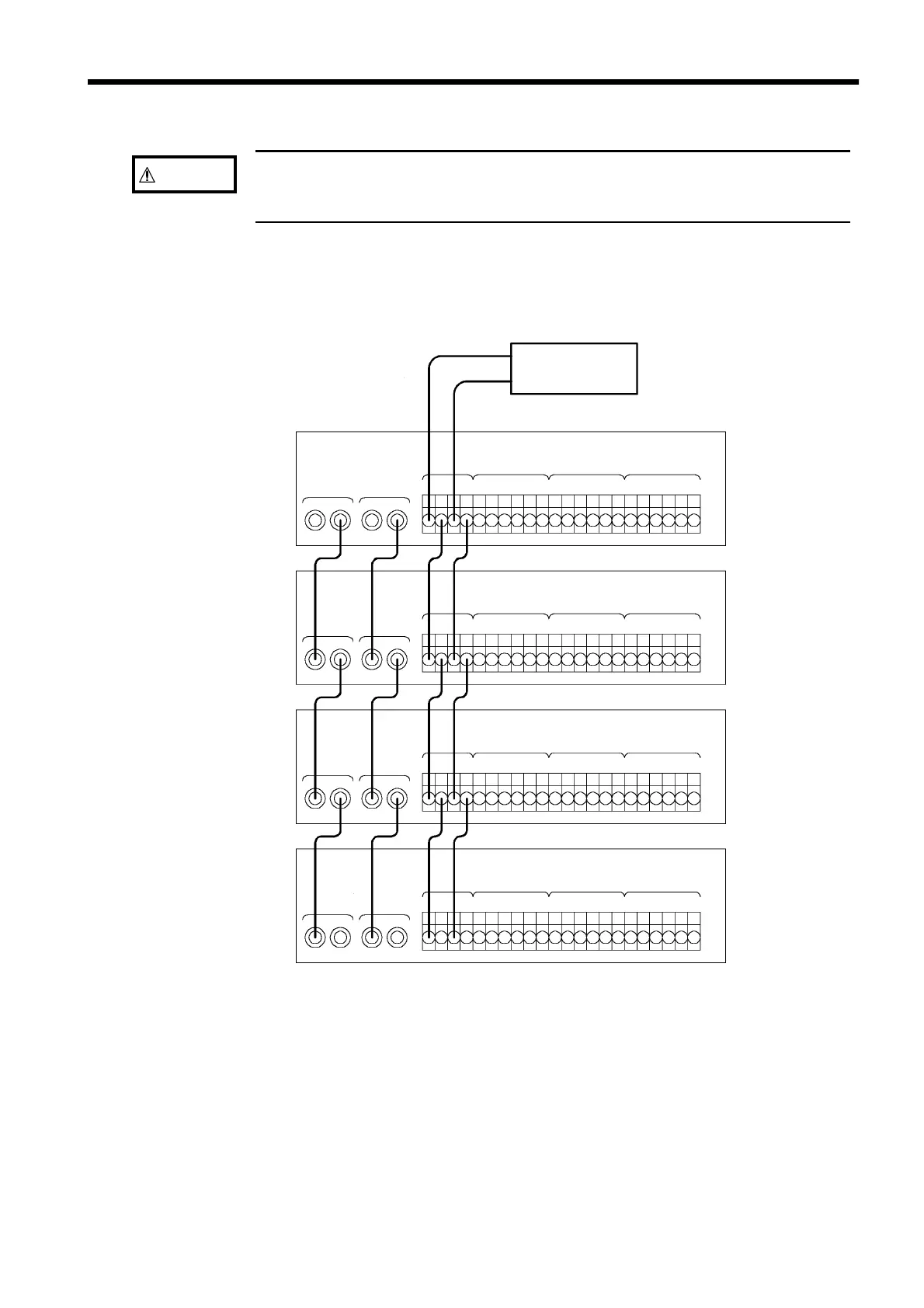
Computer
BNC
cables
within 1.5 m
Leads
within 1.0 m
Leads
within 1.0 m
Leads
within 1.0 m
Master
Slave 1
Slave 2
Slave 3
BNC
cables
within 1.5 m
BNC
cables
within 1.5 m
Leads within 1 m
Example of connecting
The MASTER CLK, SYNC CLK and RUN/STOP signals are each connected
by daisy chaining the units together.