177
Conguring Alarms
Unit Measure Channel Trigger Alarm Calculation System
*3: Slope example
With a level of 5°C and a time of 5 s
1. With a recording interval of 5 s
An alarm will be output if the current measured value diers from the previous measured value by more
than 5°C.
Example data: 20°C, 25.1°C
2. With a recording interval of 1 s
An alarm will be output if the current measured value diers from the previous measured value by more
than 1°C for ve data points in a row.
Example data: 20°C, 21.1°C, 22.2°C, 23.3°C, 24.4°C, 25.5°C
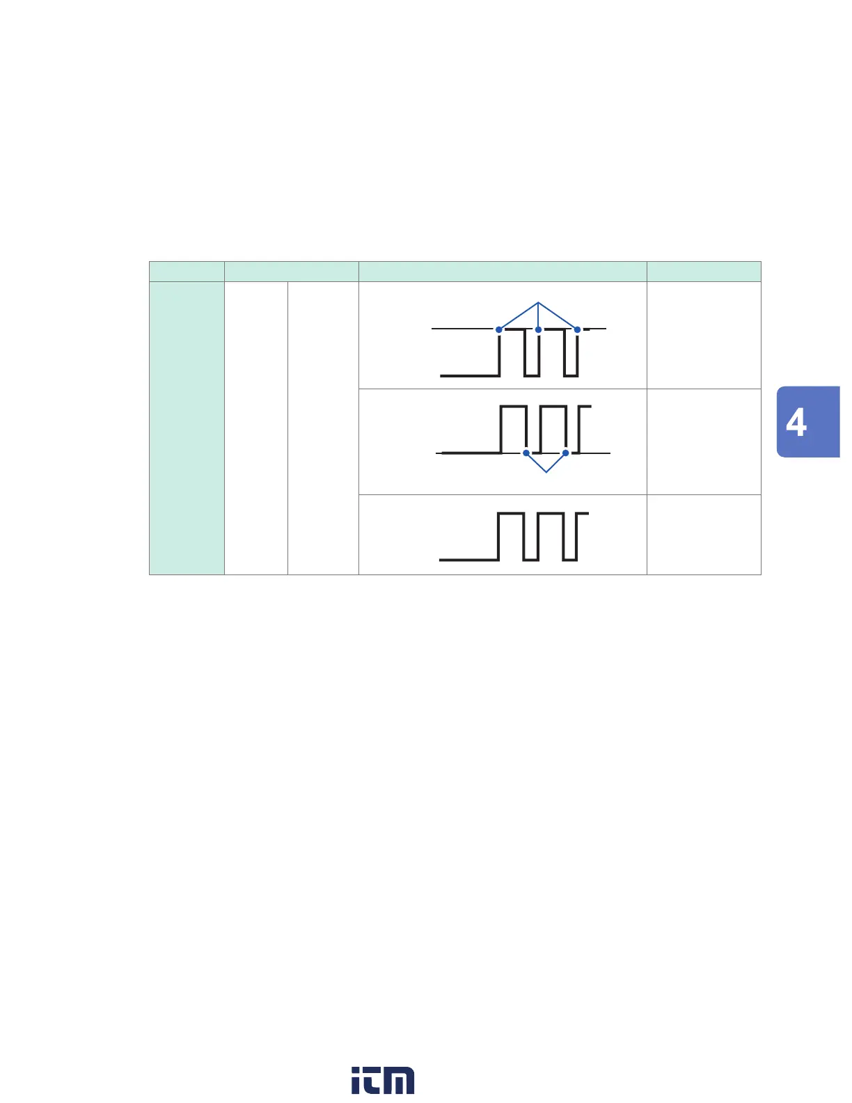
Alarm type Setting description Operation Description
Pattern Level 1, 0, X
High
Low
Alarm
[1] Outputs an alarm
when the logic
signal is 1 (high).
High
Low
Alarm
[0] Outputs an alarm
when the logic
signal is 0 (low).
High
Low
[X] Not used in alarm
judgments.
Ignores the signal.
Alarm (Alarm Output)
w ww . . co m
information@itm.com1.800.561.8187