8.2 Conguring Alarm Output (ALARM)
This section describes how to set the voltage level for the signal that is output when an alarm
condition is satised.
For more information about alarms, see “4 Alarm (Alarm Output)” (p. 171).
> >
1
1
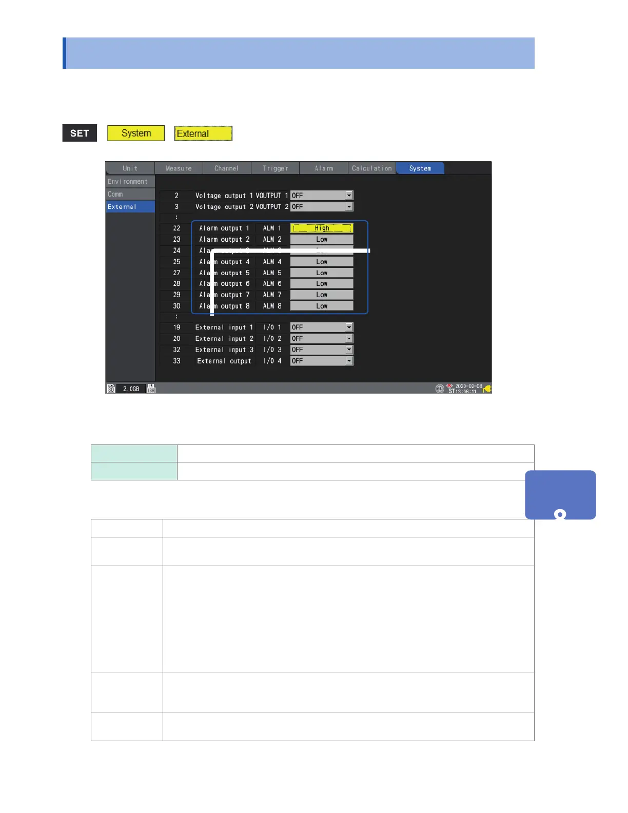
Under [Alarm output 1] to [Alarm output 8], select the voltage level you wish to output when
outputting an alarm.
Low
Outputs the alarm at low level (0 V to 0.5 V).
High Outputs the alarm at high level (4.0 V to 5.0 V).
Alarm output terminal specications
Output type Open-drain output (with 5 V voltage output)
Output voltage High level: 4.0 to 5.0 V; low level: 0 to 0.5 V
Switchable between high and low level output
Output
response time
When using the plug-in modules:
(Recording interval or data refresh interval, whichever is longer) × 2 + 1 ms
+ (analog response time)*
When using the wireless modules (LR8450-01 only):
(Recording interval or data refresh interval, whichever is longer) × 2
+ (wireless response time)*
2
+ (analog response time)*
1
*1: Varies with lter setting (U8554: 5 ms, with 120 Hz low-pass lter)
*2:
Depending on the number of connected modules (3 s when one wireless module is
connected).
Maximum
switching
capacity
5 V to 30 V DC, 200 mA
Output pulse
width
10 ms or greater
External Control (EXT. I/O)
w ww . . co m
information@itm.com1.800.561.8187