35
Conguring Input Channels
Measuring resistance
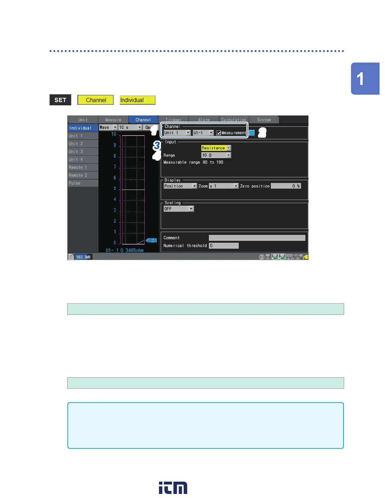
This section describes how to congure settings on the individual settings screen when measuring
resistance.
You can use [Input] on the settings list screen to congure the settings. (See p. 67.)
Applicable modules: U8551, LR8531
> >
3
1
4
2
1
Select the module (Unit) and channel to congure and select the check box.
Measurement will not be performed for channels whose check boxes are not selected.
2
Select the waveform display color.
× (OFF), 24 colors
Select [×] if you wish to measure the channel but not to display its waveform or numerical values on the
screen.
3
Set the input type to [Resistance].
4
Under [Range], select the measurement range as appropriate for the resistance being
measured.
The measurable range of the selected range will be displayed.
10
Ω
, 20
Ω
, 100
Ω
, 200
Ω
IMPORTANT
When measuring an inductive load such as winding resistance, the instrument’s response may
not be able to keep up, preventing accurate measurement. If you encounter this issue, increase
the data refresh interval. As a general rule, inductors of up to 100 mH can be measured with a
data refresh interval of 100 ms.
Settings and Operation
w ww . . co m
information@itm.com1.800.561.8187