377
Measuring Strain
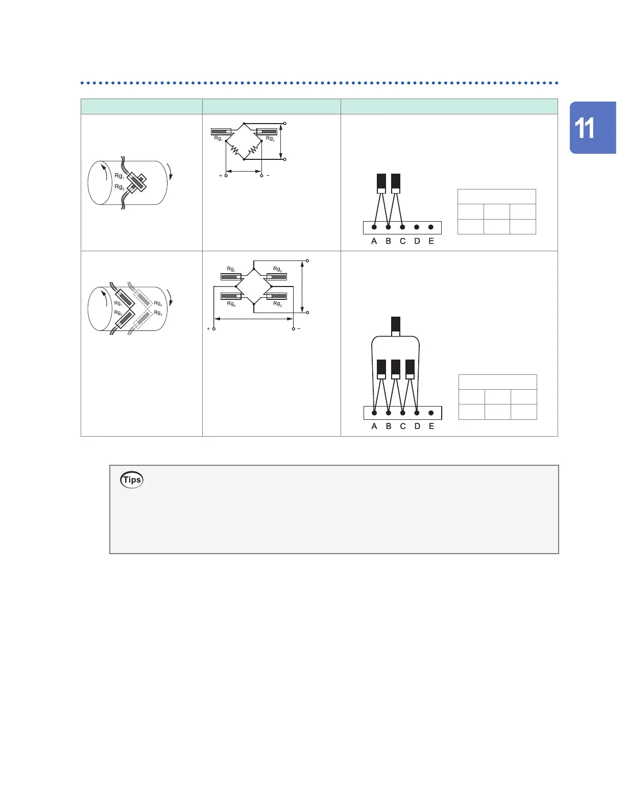
Torsional stress
Gage method Bridge circuit diagram Remarks
2-gage method
(adjacent side)
(torsion strain)
Applied voltage
E
Output
voltage
e
e = 2
ε
When measuring strain in the rotational direction,
two strain gages are oset so that they intersect
at an angle of 90°. Use a scaling conversion ratio
slope of 1/2.
DIP switch
ON ON OFF
1 2 3
Rg
1
Rg
2
4-gage method
(torsion strain)
Applied voltage
E
Output
voltage
e
e = 4
ε
This connection method is not aected by
temperature changes of the measurement target or
tension/compression/bending strain. Use a scaling
conversion ratio slope of 1/4.
DIP switch
ON OFF OFF
1 2 3
Rg
4
Rg
2
Rg
1
Rg
3
Even in measurements that are aected by temperature, you can compensate for temperature
by using a self-temperature-compensated strain gage. Longer wires are more susceptible
to the eects of temperature. Long wiring runs make lead wires susceptible to the eects of
temperature. You can make measurements with a high degree of precision by using wireless
modules to shorten wiring lengths.
For information about self temperature-compensated strain gages, contact your strain gage’s
manufacturer.
Knowledge and Information
w ww . . co m
information@itm.com1.800.561.8187