74
Conguring Channels in a List
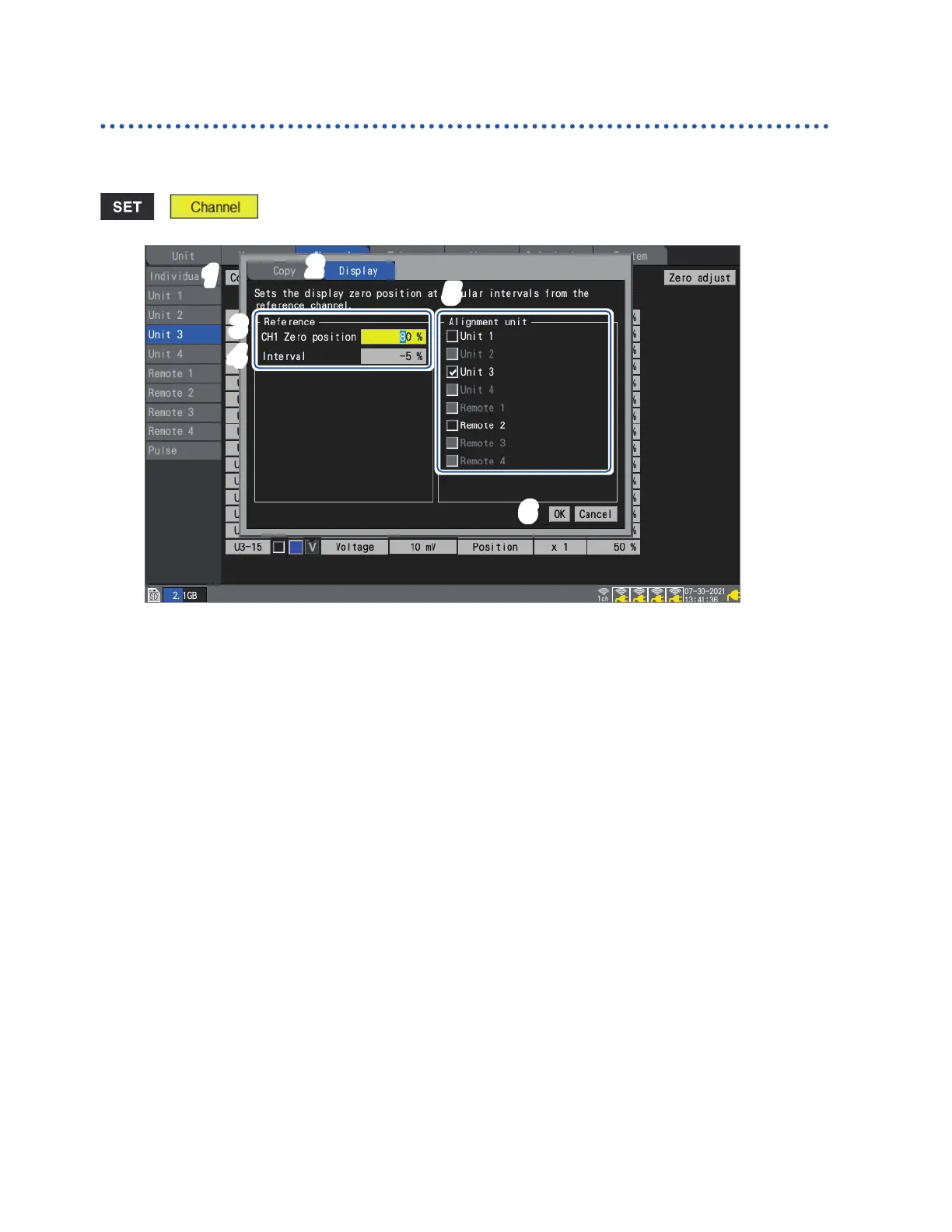
Aligning waveforms’ zero positions
This section describes how to align zero positions for displayed waveforms at a specied interval
based on channel 1 of the sub tab unit.
> > [Unit n] (n = 1, 2, . . .)
1
3
6
2
5
4
1
Press the ENTER key while [Copy…] is selected.
The settings window will open.
2
Using the up and down keys, select the [Display] tab.
3
Under [CH1 Zero position] under [Reference], set the zero position for the reference channel
(CH1).
4
Under [Interval] under [Reference], set the interval for uniform alignment.
5
Under [Alignment unit], select the checkboxes for the units whose zero positions you wish
to align.
6
Select [OK] and press the ENTER key.
• Alignment is only valid for the reference channel and channels whose copy destination channel
display setting is [Position].
• The range for the reference channel’s zero position varies with the zoom factor.
• If [Interval] is negative, zero positions will be shifted from the reference channel’s zero position
in the negative direction at a set interval; if it’s positive, they’ll be shifted similarly in the positive
direction.
• Alignment is valid for units with the same number of channels in the same system.
U8550 and LR8530 (Voltage/Temp Units, 15 channels of plug-in and wireless modules)
U8551 and LR8531 (Universal Units, 15 channels of plug-in and wireless modules)
U8552 and LR8532 (Voltage/Temp Units, 30 channels of plug-in and wireless modules)
U8553 and LR8533 (High Speed Voltage Units, 5 channels of plug-in and wireless modules)
U8554 and LR8534 (Strain Units, 5 channels of plug-in and wireless modules)
• If the maximum or minimum value for the zero position is exceeded due to the zoom factor at the
time of alignment, the maximum or minimum value will be used.
w ww . . co m
information@itm.com1.800.561.8187