406
Input Circuit Schematics
11.13 Input Circuit Schematics
This section provides input circuit schematics for the instrument.
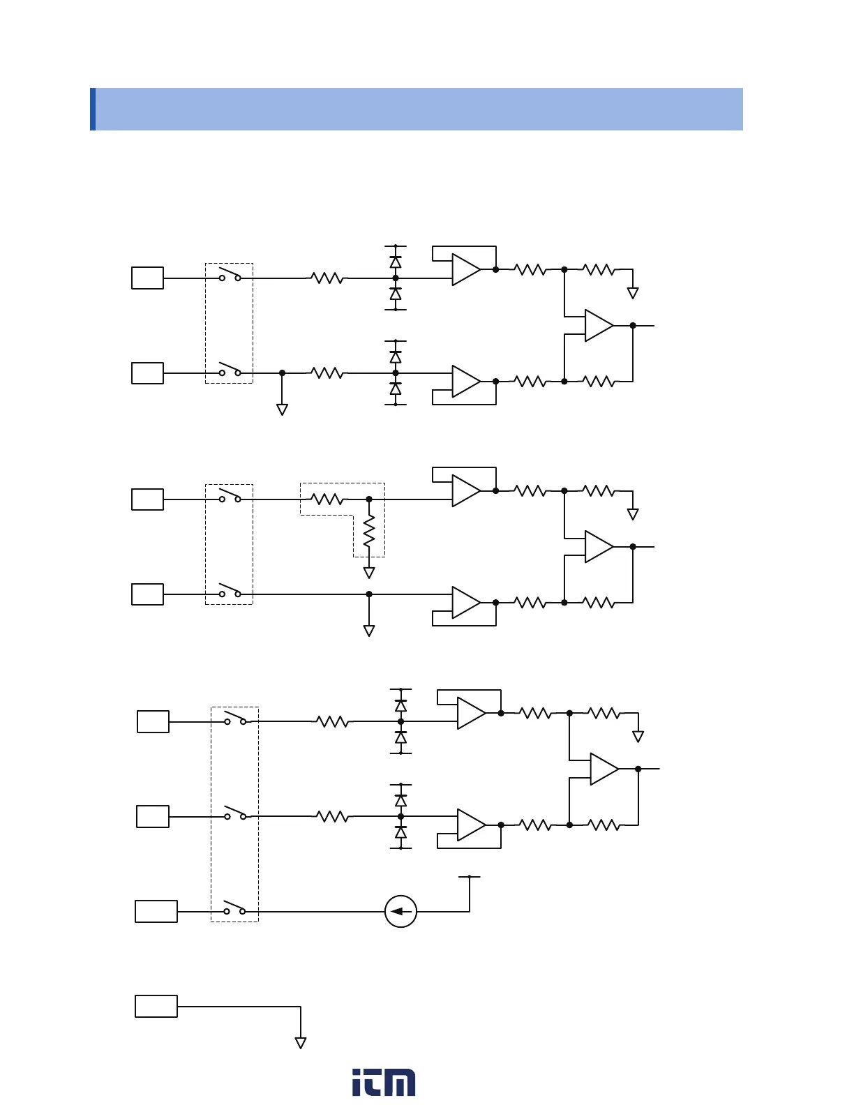
Analog input circuit: U8550, U8551, U8552, LR8530, LR8531, LR8532
• Voltage (10 mV f.s. to 2 V f.s. ranges), thermocouple
+
-
Channel switching relay
• Voltage (10 V f.s. to 100 V f.s. ranges, 1-5 V f.s. range), humidity
+
-
Channel switching relay
1 M
Ω
• Resistance temperature detector (4-wire), resistance
+
-
SoH
SoL
Channel switching relay
Constant-current circuit
SoL terminal is common to all channels.
w ww . . co m
information@itm.com1.800.561.8187
 Loading...