226
Conguring Alarm Output (ALARM)
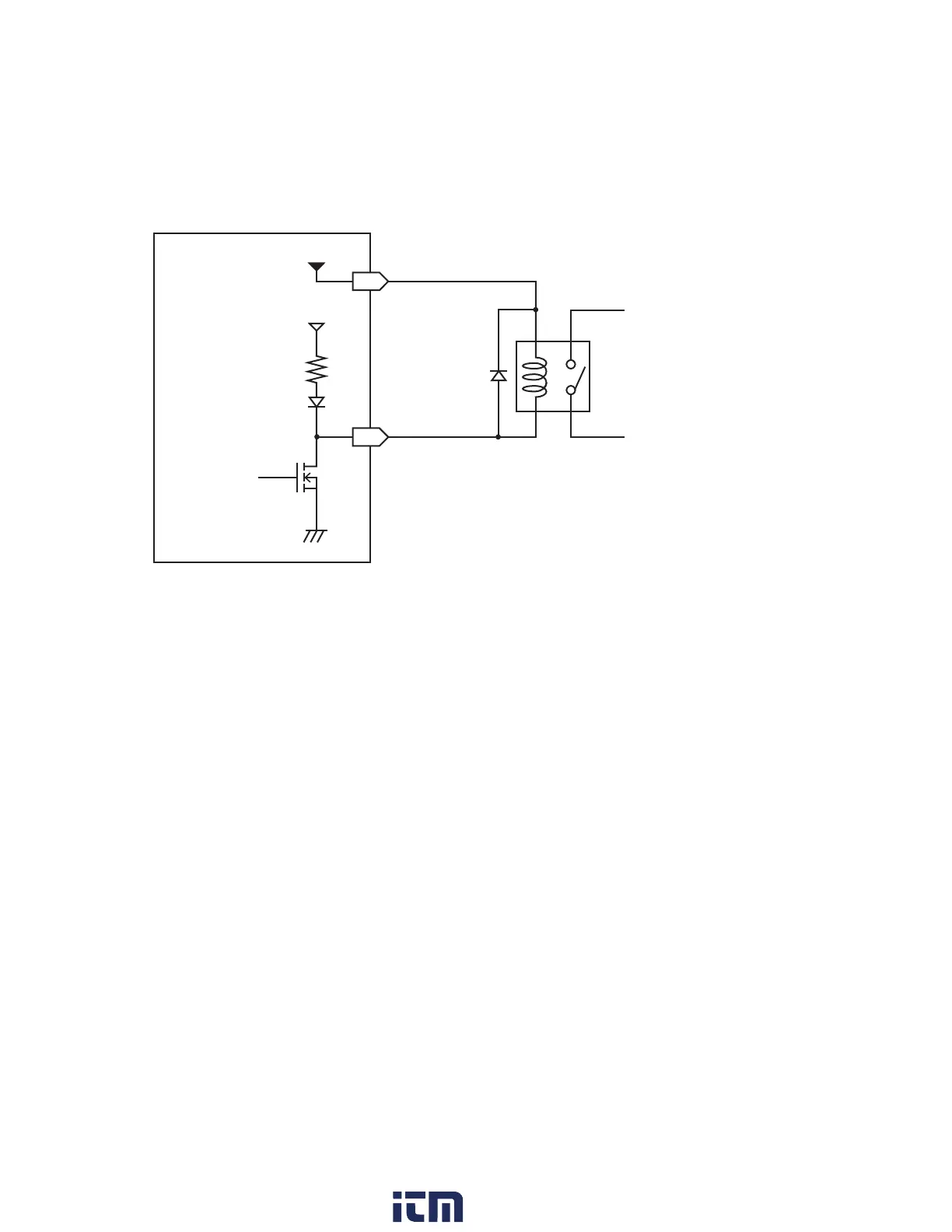
Alarm output terminal circuit diagram and example connection
Select the relay with the contact conguration to perform the desired operation.
The example connection illustrates a circuit in which the relay will operate when the alarm output is
low.
VOUTPUT
Max. 200 mA
Max. 100 mA
Instrument
5 V DC
10 k
Ω
GND
Relay
Select the appropriate VOUTPUT
voltage for the relay coil’s rated voltage.
ALARM
+
−
w ww . . co m
information@itm.com1.800.561.8187