231
Conguring External Input/Output (I/O) Terminals
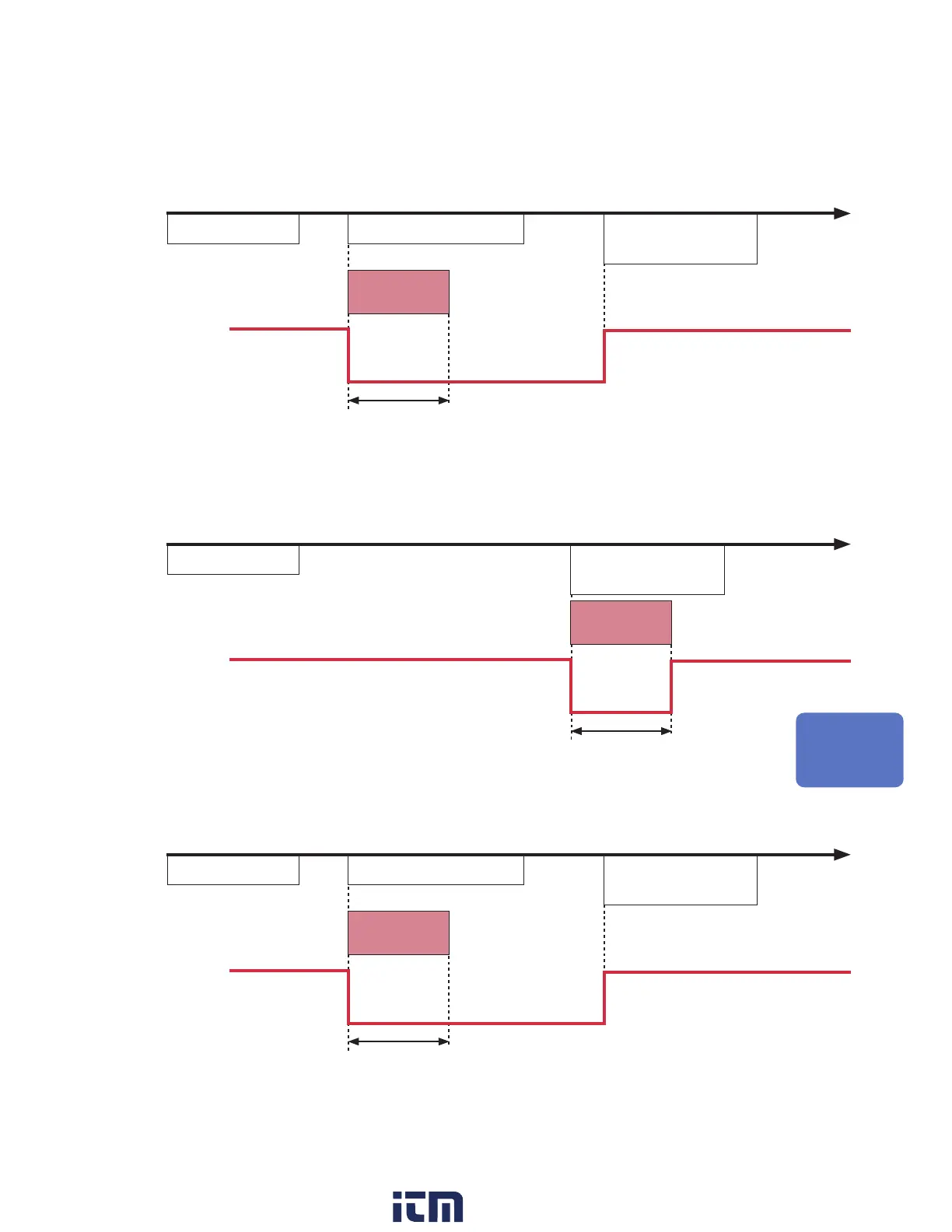
Trigger output timing
The timing at which signals appear in trigger output varies with the [Timing] setting.
See “2.2 Enabling the Trigger Function” (p. 116).
Start
Measurement start Start trigger activated
Measurement stop
= Acquisition complete
To next
measurement
Minimum
pulse width
Trigger output waveform
10 ms or greater
Level held during
measurement
• Trigger output will switch to active when the start trigger activates.
• The pulse will be output for at least 10 ms and held while measurement continues.
• Trigger output will switch to non-active when measurement stops.
Stop
Measurement start
Stop trigger activated
= Acquisition complete
To next
measurement
Minimum
pulse width
Trigger output waveform
10 ms or greater
• Trigger output will switch to active when the stop trigger activates.
• The pulse will be output for at least 10 ms, and then trigger output will switch to non-active.
Start & stop
Measurement start Start trigger activated
Stop trigger activated
= Acquisition complete
To next
measurement
Minimum
pulse width
Trigger output waveform
10 ms or greater
Level held during
measurement
• Trigger output will switch to active when the start trigger activates.
• The pulse will be output for at least 10 ms and held while measurement continues.
• Trigger output will switch to non-active when the stop trigger activates.
External Control (EXT. I/O)
w ww . . co m
information@itm.com1.800.561.8187