368
Options
Z3230 Wireless LAN Adapter
Z1007 Battery Pack
C1012 Carrying Case
2. Input, output, and measurement specications
-1. Basic specications
Number of CAN ports 2 ports
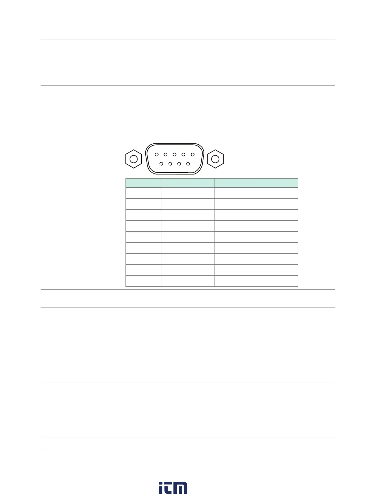
Input terminal
1 2 3 4
6 7 8 9
5
Pin Assignment Functionality
1 N.C. Unused
2 CAN_L CAN_L communications line
3 GND Ground
4 N.C. Unused
5 N.C. Unused
6 N.C. Unused
7 CAN_H CAN_H communications line
8 N.C. Unused
N.C. Unused
Power supply
receptacle
USB port (Series A receptacle) ×2
Interface CAN
Terminator Can be enabled/disabled for each port.
Resistance value: 120
±10
ACT LED Displays the CAN bus operating status.
TERM LED Illuminates when the terminator is enabled.
Data refresh interval 10 ms, 20 ms, 50 ms, 100 ms, 200 ms, 500 ms, 1 s, 2 s, 5 s, 10 s
Baud rate
Sampling point
ACK
Operating mode Only receive mode is supported.
w ww . . co m
information@itm.com1.800.561.8187