386
Noise Countermeasures
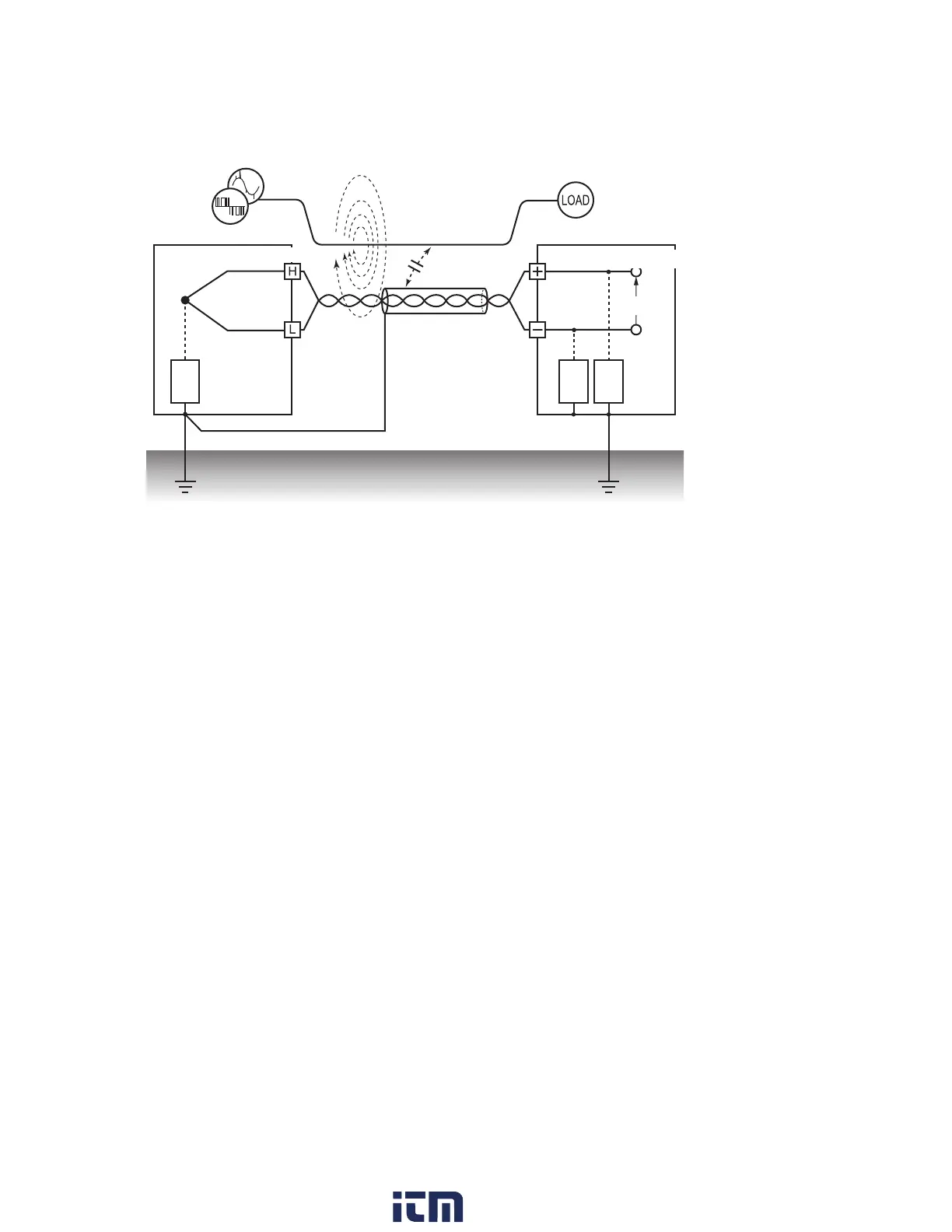
Normal-mode noise countermeasures
Device under measurement
Measurement module
Thermocouple
Ground shielded wires on the signal side.
Capacitive
coupling
Inverter or commercial
power supply
Electromagnetic
coupling
Shielded
Twisted-pair wire
Power line
Vin
Z
1
Z
2
Z
3
Keep signal lines (thermocouples) away from wires that could serve as sources of noise (power supply lines,
etc.). Furthermore, you can block capacitive coupling by shielding and grounding signal lines.
• Isolate circuits from sources of noise (measure temperature using thermocouples).
Input channels are isolated from the enclosure and from each other. You can measure a
conductor with a potential by directly axing a thermocouple, up to the maximum rated terminal-
to-ground voltage.
Eective methods for dealing with the eects of noise include wrapping the thermocouple in high-
heat-resistance tape to insulate it or isolating input lines with non-grounded thermocouples.
• Use a lter.
You can reject noise that has contaminated input signals by using the power supply frequency
lter.
It is recommended to select the same frequency (50 Hz or 60 Hz) as the power supply frequency
in the region where the instrument is being used.
See “7.1 Conguring Settings” (p. 212).
The U8554 and LR8534 provide a low-pass lter.
Set the low-pass lter’s cuto frequency so that it’s lower than the power supply frequency.
w ww . . co m
information@itm.com1.800.561.8187