Number Item Description
6
PATH (IN) connector Connects to a controller or
drive tray.
7
PATH (OUT)LED Blue: OUT side port is linked
up.
8
PATH (OUT) connector Connects to a drive tray.
9
Console This port is reserved.
10
Power supply unit
N/A
11
Receptacle Connects to the power cable
provided with the storage
system.
12
AC IN LED Green: Normal operation.
13
ALM LED Red: Power supply unit can be
replaced.
14
RDY LED Green: Normal operation.
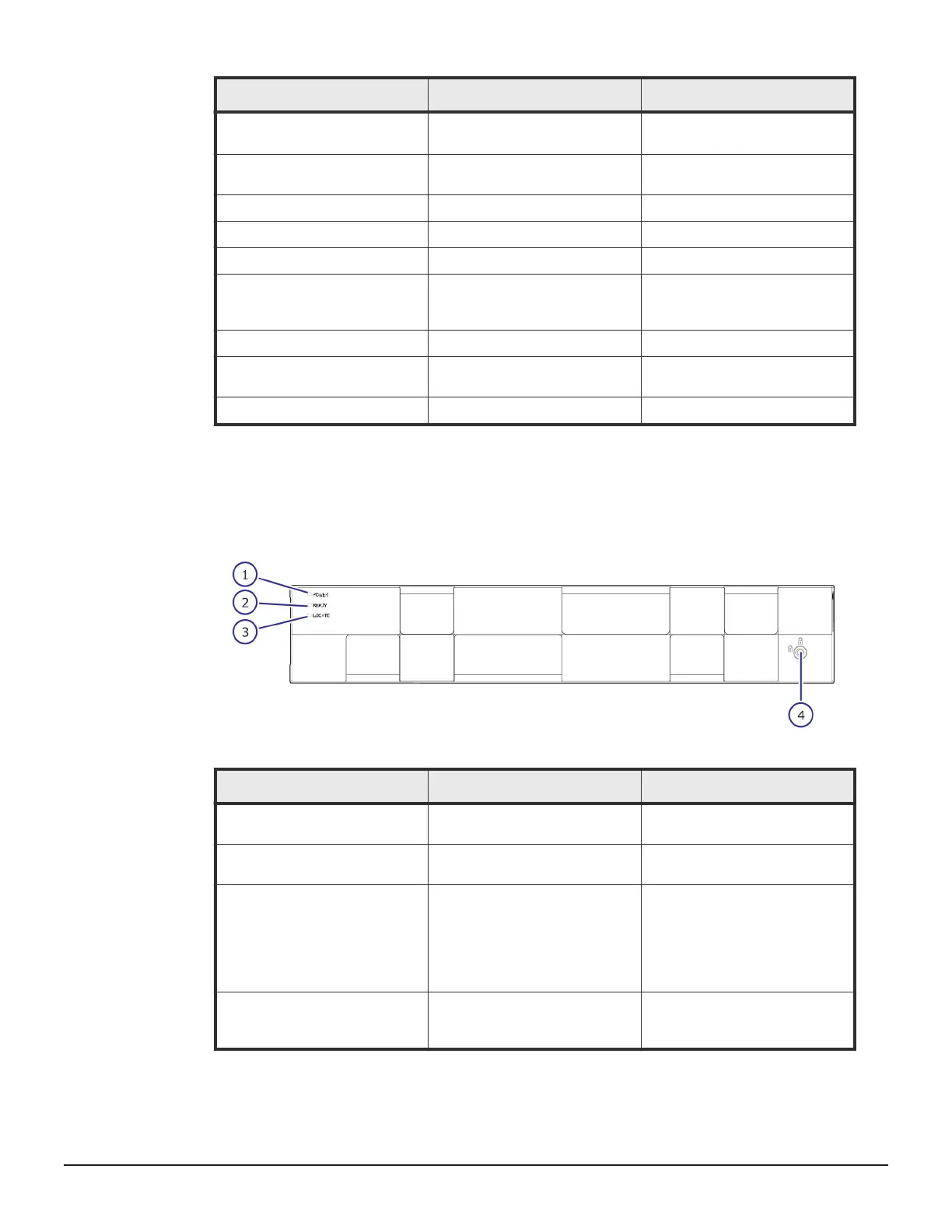
Flash module drive (FMD) tray
FMD with front panel bezel
Number
Item Description
1
POWER LED Green: Drive tray is powered
on.
2
READY LED Green: Drive tray is
operational.
3
LOCATE LED Amber:
• Indicates the location of the
chassis.
• Can be turned on or turned
off by the maintenance
utility.
4
Lock Locks and unlocks the front
panel bezel by using the
supplied key.
62 Hardware description
Service Guide for VSP Gx00 and VSP Fx00 Models

 Loading...