EQUIP
®
Series ACUIX™ IP PTZ Dome Installation and Configuration Guide
Document 800-04194V1 Rev A 19
07/11
To set the baud rate and parity:
•Using Table 3-3 and Table 3-4 as a reference, position the pins on switch
SW6 to correspond to the baud rate and parity values of the protocol that
you have selected.
If any of the settings on SW5 or SW6 are invalid, the system reverts to the
factory default settings: MAXPRO-mode at 9600 baud, even parity.
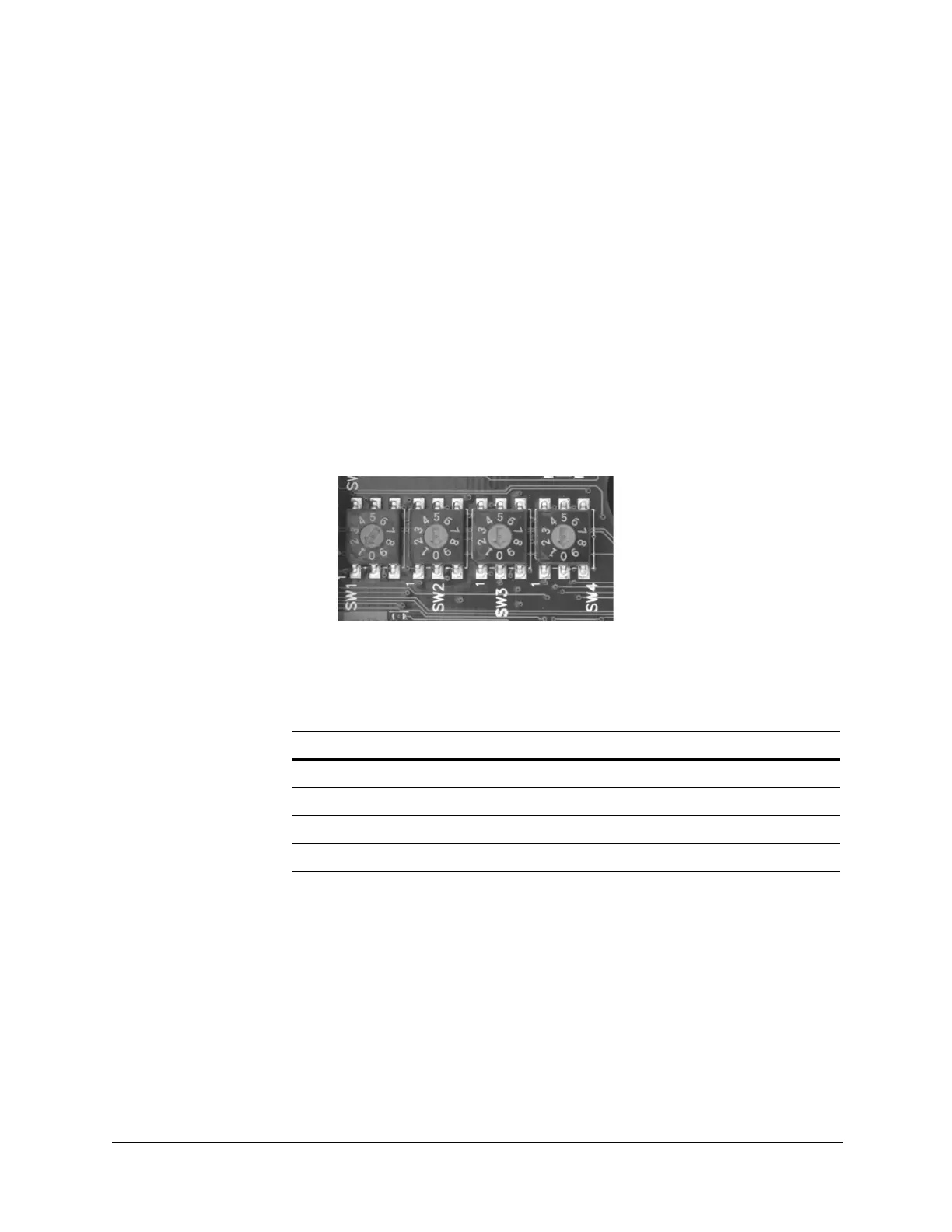
Setting the Dome Address (SW1 to SW4)
The dome address for all scan assemblies should be set to 0001. The address
is set using the rotary DIP switches SW1, SW2, SW3, and SW4 on the scan
assembly main board (see Figure 3-1 and Figure 3-2).
Figure 3-2 Switches SW1 to SW4
Each switch is assigned a place value (see Table 3-5).
To set the dome address to 0001:
• Set SW1=1, SW2=0, SW3=0, SW4=0.
Table 3-5 Address Switch Assignments
Address Value
SW1 Units digit
SW2 Tens digit
SW3 Hundreds digit
SW4 Thousands digit
 Loading...