4. Series 8 IOTA Pinouts
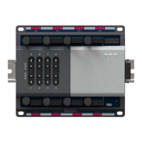
4.2. Differential Analog input IOTA (Models 8X-TAIDA1 and 8X-TAIDB1)
62 Series 8 I/O User's Guide R500
Honeywell April 2017
Self-powered 3-wire transmitter (system ground)
Self-powered transmitter is connected across the TB1-1 and TB2-2 when the common
terminal is terminated at TB2–16. Configure the default jumper settings as single-
ended according to the Table 15 Series 8 differential Analog Input 9 inch and 12 inch
IOTAs – terminal block 2.
Voltage input (System ground)
Voltage output transducer is connected across TB1-2 and TB2-16 as illustrated in the
following figure. To use voltage output transducer, disconnect the 250Ω spool resistor

 Loading...


