Chapter 6
Removing and Replacing Components
Removing and Replacing a Dual Processor Module
196
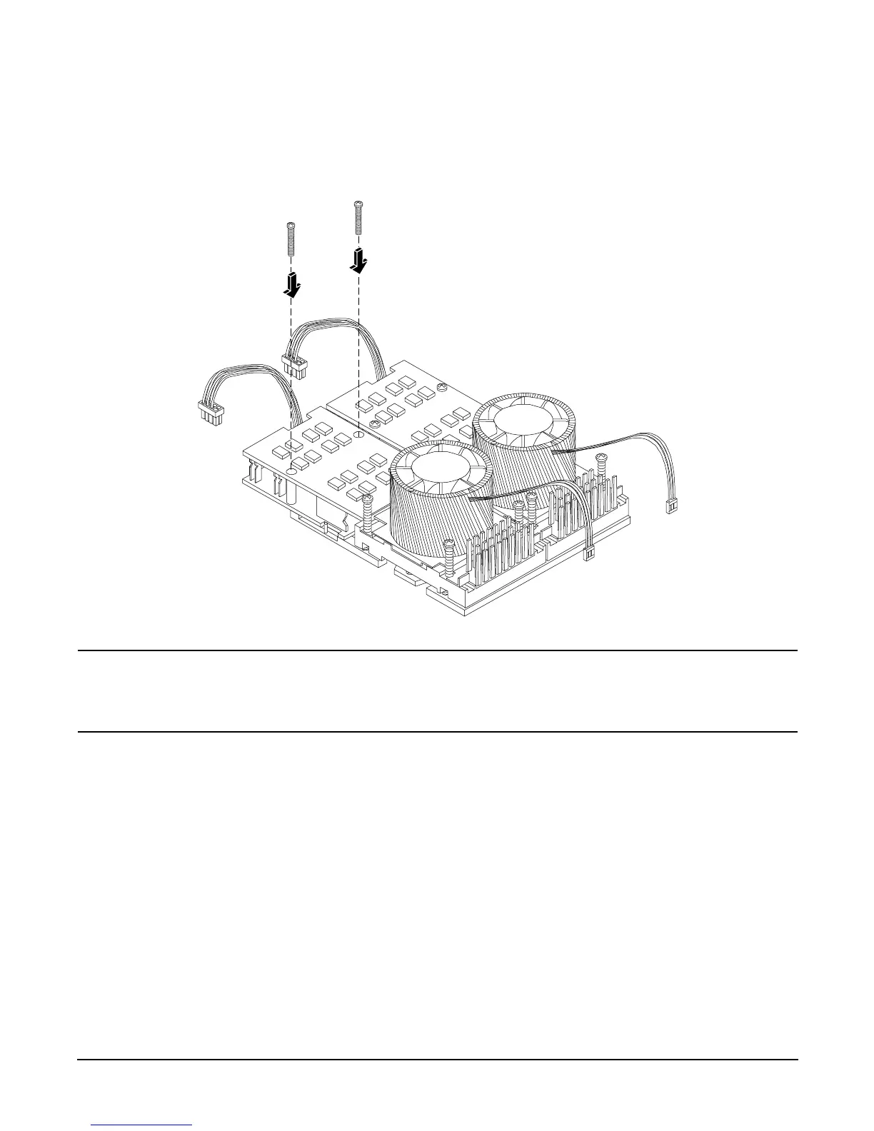
Step 12. Align the two mounting screw holes on the power module with the screw holes in the shims on the
system board’s metal mounting bracket (Figure 6-49). Screw in the power module mounting screws
(Figure 6-50). (Use the screws removed in step 10.)
Figure 6-50 Installing the Processor Module Power Pod Mounting Screws
CAUTION Turbo fan power cables can be damaged if pinched between the heatsink posts and
the processor airflow guide. Ensure the cables are below the top surface of the
heatsink posts before installing the processor airflow guide by routing the cables
through the heatsink posts (Figure 6-51).
 Loading...


