243
• Capture 10 incoming packets on GigabitEthernet 1/0/1 and save the packets to a packet file.
• Display contents in the file.
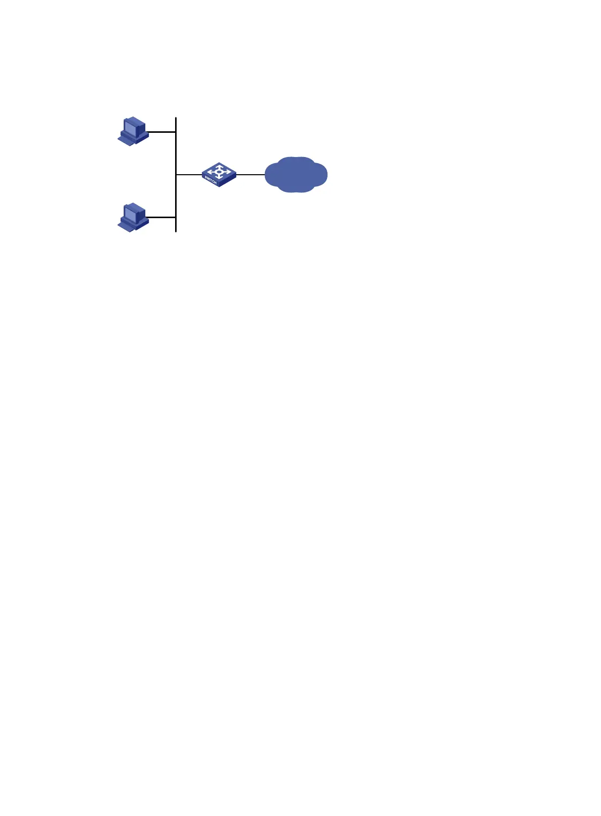
Figure 24 Network diagram
Configuration procedure
# Capture packets on GigabitEthernet 1/0/1. Set the maximum number of captured packets to 10.
Save the packets to the file flash:/a.pcap.
<DeviceA> packet-capture interface gigabitethernet1/0/1 limit-captured-frames 10 write
flash:/a.pcap
Capturing on Gigabitethernet1/0/1
10
# Display the contents in the packet file.
<DeviceA> packet-capture read flash:/a.pcap
1 0.000000 192.168.56.1 -> 192.168.56.2 TCP 62 6325 > telnet [SYN] Seq=0 Win
=65535 Len=0 MSS=1460 SACK_PERM=1
2 0.000061 192.168.56.1 -> 192.168.56.2 TCP 60 6325 > telnet [ACK] Seq=1 Ack
=1 Win=65535 Len=0
3 0.024370 192.168.56.1 -> 192.168.56.2 TELNET 60 Telnet Data ...
4 0.024449 192.168.56.1 -> 192.168.56.2 TELNET 78 Telnet Data ...
5 0.025766 192.168.56.1 -> 192.168.56.2 TELNET 65 Telnet Data ...
6 0.035096 192.168.56.1 -> 192.168.56.2 TELNET 60 Telnet Data ...
7 0.047317 192.168.56.1 -> 192.168.56.2 TCP 60 6325 > telnet [ACK] Seq=42 Ac
k=434 Win=65102 Len=0
8 0.050994 192.168.56.1 -> 192.168.56.2 TCP 60 6325 > telnet [ACK] Seq=42 Ac
k=436 Win=65100 Len=0
9 0.052401 192.168.56.1 -> 192.168.56.2 TCP 60 6325 > telnet [ACK] Seq=42 Ac
k=438 Win=65098 Len=0
10 0.057736 192.168.56.1 -> 192.168.56.2 TCP 60 6325 > telnet [ACK] Seq=42 Ac
k=440 Win=65096 Len=0
SwitchA
GE1/0/2
GE1/0/1
HostA
192.168.56.1/24
Internet
HostB
192.168.56.2/24

 Loading...


