18-1
18� ADVANCED CONNECTIONS
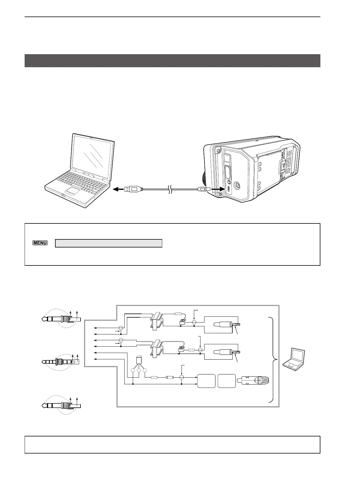
FSK and AFSK connections
The transceiver has a mode key for RTTY. You can use a PC and an application software to operate
RTTY using a USB cable. See the interface circuit diagram below for details.
Refer to the software application’s instruction manual for setup details.
( Icom does not guarantee the performance of the application software, PC, network device, or network
settings.)
TIP:
• To operate RTTY through your PC’s USB port, set the following item.
»
SET > Connectors > USB SEND/Keying
• Download the USB driver and the installation guide from the Icom website.
https://www�icomjapan�com/support/
To a USB port
To the [microUSB] port
USB cable
PC
When using the microUSB port
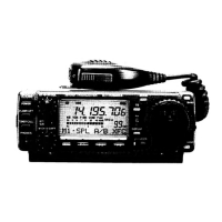
When using the [SP] jack, [MIC] jack, and [SEND/ALC] jack
TIP: We recommend using the SEND terminal on the [SEND] jack to change receiving and transmitting.
If you use the PTT terminal on the [MIC] jack, the data may be cut off.
PC
CE B
Connect to
LINE IN or
MIC IN
Connect to
SP OUT
No connection
No connection
Shield cable
Shield cable
Shield cable
2kΩ:2kΩ 10kΩ
2kΩ:2kΩ
10kΩ
4.7kΩ
RTS
GND
10kΩ
(Trimpot)
10kΩ
(Trimpot)
Connect to
COM port
D-Sub25
D-Sub9
Pin 4
Pin 7
Pin 7
Pin 5
Shield cable
Shield cable
★1: NPN transistor
(2SC1815)
★2: Switching diode
(1S1588)
★1
★2
F
D
C
A
B
2.5 mm
Connecting to [MIC]
CD
E
3.5 mm (1/8 inch)
Connecting to
[
SEND/ALC
]
FE
3.5 mm (1/8 inch)
Connecting to [SP]
BA
Interface circuit example for digital modes (User supplied)