5: CPU CONFIGURATION (FUN)
USER’S MANUAL 5-7
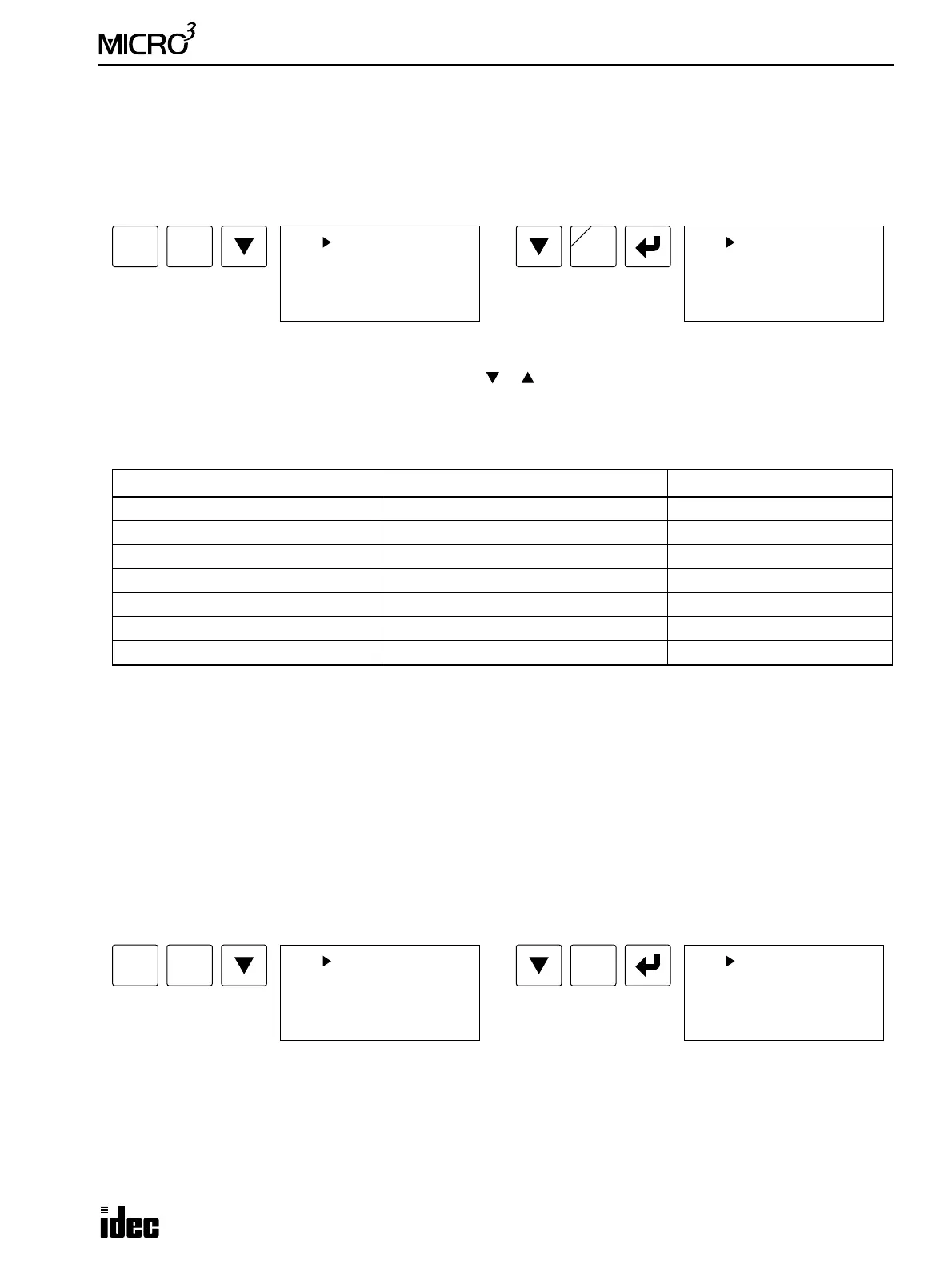
FUN8: Loader Port Communication Mode Setting
The MICRO
3
or MICRO
3
C base unit can communicate with a personal computer or modem through the RS485 loader port
(MICRO
3
) or the RS232C loader port (MICRO
3
C). For this, the communication format can be selected from the standard or
optional mode. When the mode selection input selected by FUN8 is turned on, the optional communication mode is
enabled. When using the program loader to communicate with the MICRO
3
or MICRO
3
C base unit, use the standard com-
munication mode of all default values.
Pressing the REP key toggles the options for each parameter.
To move the cursor from a parameter to another, press the or key.
To restore the default value, move the cursor to the parameter, and press the DEL key.
Pressing the DEL key with the cursor placed at the mode input selection on the bottom line, the input selection is cleared,
and the optional communication mode is canceled.
To return to the editor mode, press the CLR key.
Note 1: When the protocol selector switch is set to 1 or 3 to select user protocol for the loader port on the MICRO
3
C, the
mode selection input is not used and need not be specified to enable the FUN8 value.
Note 2: When 2550 is selected, receive timeout is disabled in the user communication of the MICRO
3
C.
FUN9: PLC Address for Network Communication
The MICRO
3
or MICRO
3
C base unit can be connected to a personal computer through the RS485 loader port (MICRO
3
) or
the RS485 data link terminals (MICRO
3
C) for a 1:N communication computer link network. When used in a network, the
PC must have addresses to differentiate various MICRO
3
or MICRO
3
C base units that it communicates with.
Each MICRO
3
or MICRO
3
C in a network can be allocated to a unique number from 0 through 31, using FUN9. A PC will
communicate with the MICRO
3
or MICRO
3
C base units in a network, addressing to the values that have been allocated in
FUN9:
The key sequence above will allocate address 1 to the MICRO
3
or MICRO
3
C base unit being programmed.
The default selection is device number 0.
To return to the editor mode, press the CLR key.
Communication Parameter Option Default (Standard Mode)
Baud Rate 1200, 2400, 4800, 9600, 19200 bps 9600 bps
Terminator Code 0D (CR), 0D 0A (CR LF) 0D (CR)
Data Bits 7, 8 bits 7 bits
Parity Check None, Even, Odd Even
Stop Bits 1, 2 bits 1 bit
Mode Selection Input (Note 1) I0 to I15 None
Receive Timeout (Note 2) 10 to 2550 (10-msec increments) 500 msec
FUN
FUN 8 COM-FORM
* 9600bps *0D
*7bit*EVEN*stop1
(:I___ : 500ms)
REP
B
8
MCS/R
FUN 8 COM-FORM
*19200bps *0D
*7bit*EVEN*stop1
(:I___ : 500ms)
FUN
FUN 9 NUMBER
Device Number
: 0
9
JMP/E
1
BPS
FUN 9 NUMBER
Device Number
: 1