4: SPECIAL FUNCTIONS
4-2 USER’S MANUAL
Catch Input Function
The catch input function is used to receive short pulses from sensor outputs regardless of the scan time. Since input signals
to inputs I0 through I7 are always set to special internal relays M290 through M297, input signals are securely received
even if short-pulse input signals turn on and off within one scan time.
Input terminals I0 through I7 are assigned to catch inputs and also used for normal inputs. All normal input signals are read
when the END instruction is executed at the end of a scan.
Catch Input Terminals and Pulse Widths
10-I/O MICRO
3
base unit: Catch inputs 6 points (I0 through I5)
16- and 24-I/O MICRO
3
base units: Catch inputs 8 points (I0 through I7)
Minimum detectable pulse width (when hard filter is set to 10):
Input I0 ON pulse = 28 µsec, Input I0 OFF pulse = 30 µsec
Input I1 to I7 ON pulse = 37 µsec, Input I1 to I7 OFF pulse = 120 µsec
Catch Input Terminals and Special Internal Relays
Each catch input is assigned to a special internal relay to store the catch input signal. Catch input terminals are divided into
four groups to select rising or falling edges for catch inputs.
Note: The 10-I/O type MICRO
3
base unit has only inputs I4 and I5 in group G4.
Rising or Falling Edge Selection for Catch Inputs (FUN6)
FUN6 is used to select whether catch inputs are accepted at the rising edge (ON pulse) or falling edge (OFF pulse). Select
the rising or falling edge for each group using FUN6 on the program loader. For setting FUN6, see page 5-6.
Input Filter Time Selection (FUN7)
To make sure of correct receiving of catch input signals, set the input filter time using FUN7 on the program loader. Only
hard filter can be used for catch inputs. The hard filter can be set between 0 and 255 to select the detectable pulse width.
For setting FUN7, see page 5-6. For details of the input filter function, see the following pages.
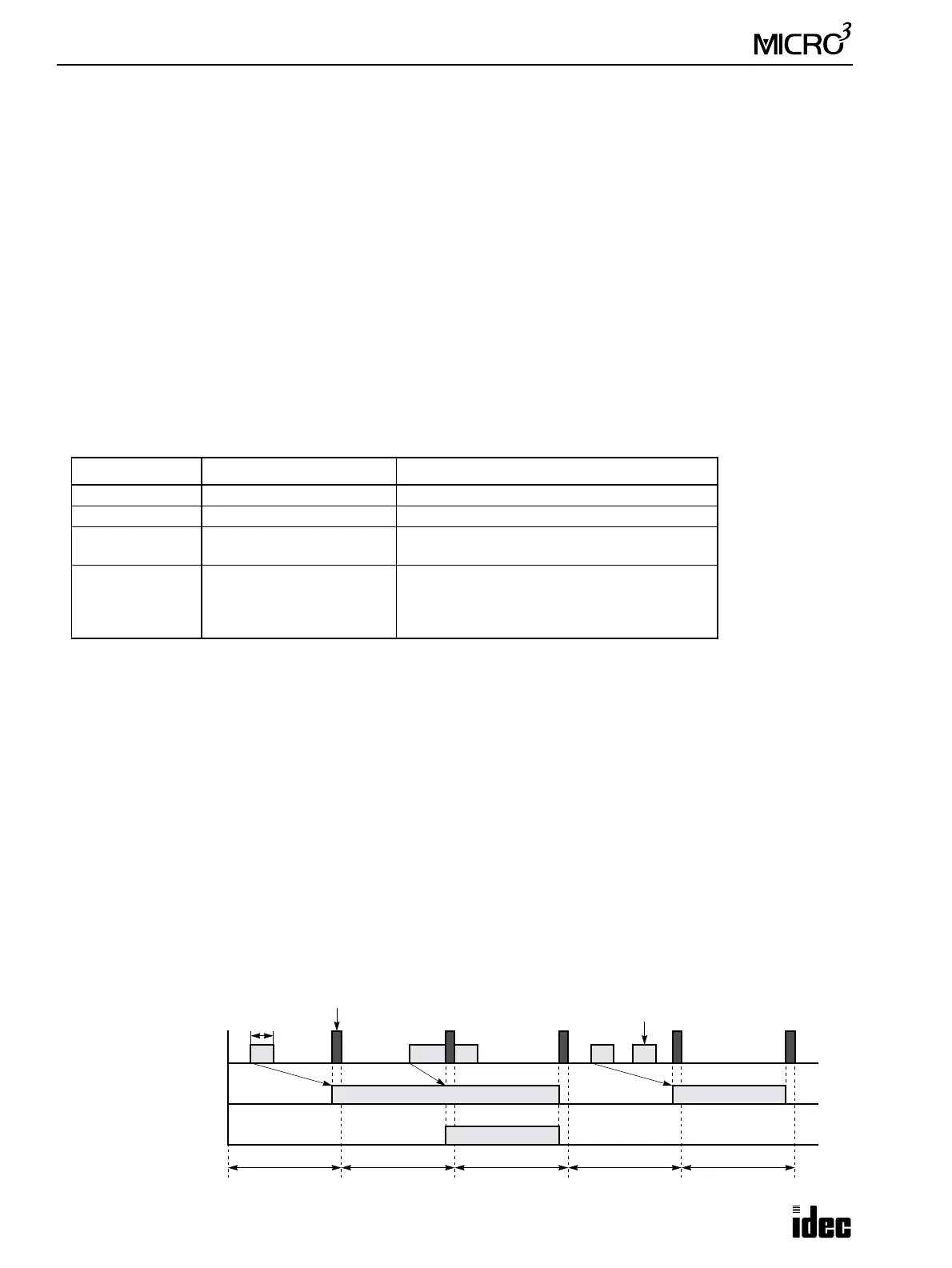
Catch Input vs Normal Input
The figure below compares how ON-pulse catch inputs and normal inputs are processed by MICRO
3
. In this example,
FUN6 is set to select the rising edge to receive ON-pulse catch inputs.
When a short-pulse input enters, the corresponding catch input special internal relay is turned on for the next one scan
time. When a catch input turns on in every scan, the corresponding catch input special internal relay remains on.
Catch Group Catch Input Number Corresponding Special Internal Relay
G1 I0 M290
G2 I1 M291
G3
I2
I3
M292
M293
G4
(see note)
I4
I5
I6
I7
M294
M295
M296
M297
Actual Input I0
ON
OFF
Input I0
ON
OFF
Inputs processed
One Scan Time
Internal Relay M290
ON
OFF
(NO contact)
(RAM)
(RAM)
One Scan Time One Scan Time One Scan Time One Scan Time
40 µsec
Remains on
Ignored