3: PROGRAM LOADER
USER’S MANUAL 3-3
Program Loader Operation Modes
The program loader has four operation modes and displays as shown below.
Editor Mode
The editor mode is used to edit a user program in the user program memory of the
program loader. See page 3-5. From the normal editor mode, the operation mode
can be changed to the address selection mode, insert mode, or delete mode.
Address selection mode: A program address is selected by pressing the ADRS key.
Insert mode: A program instruction is inserted by pressing the INS key.
Delete mode: Program instructions are deleted by pressing the DEL key.
Transfer Mode
The transfer mode is used to transfer or compare user programs between the pro-
gram loader and the MICRO
3
base unit or memory card. See page 3-9.
Monitor Mode
The monitor mode is used to monitor input, output, internal relay, shift register sta-
tuses, preset and current values of timers and counters, and data of data registers on
the program loader display. The monitor mode is also used to set or reset an input,
output, internal relay, or shift register bit from the program loader. Timer/counter
preset values and data register values are also changed using the monitor mode.
See page 3-12.
FUN (Function) Mode
The FUN mode is used to change the FUN table settings for the MICRO
3
base unit,
program loader, and memory card. See page page 5-1.
Internal Memory and User Memory
When a user program and FUN settings are edited using the program loader, the data is stored in the internal RAM of the
program loader. When the user program is transferred to the MICRO
3
base unit, FUN1 through FUN11 settings are also
transferred.
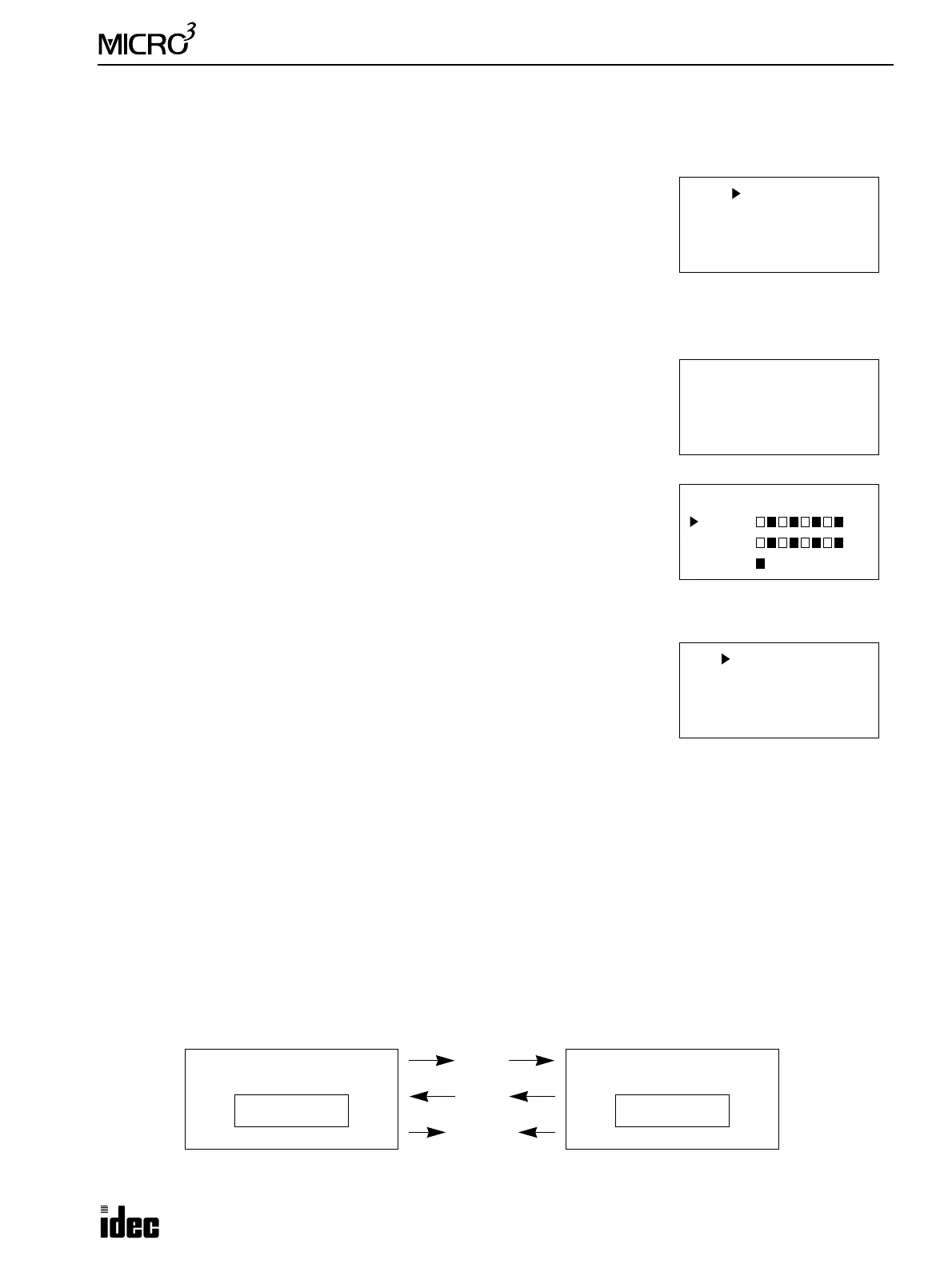
When program transfer and verification are performed, the user program moves as follows:
Write: The user program and FUN1 through FUN11 settings are written from the program loader to the EEPROM in
the MICRO
3
base unit.
Read: The user program and FUN1 through FUN11 settings are read from the MICRO
3
base unit to the internal RAM
of the program loader.
Verify: User programs and FUN1 through FUN11 settings are compared between the MICRO
3
base unit and the internal
RAM of the program loader.
0 LOD I 0
1 LOD I 1
2 CNT 2 10
4 C 2= 5
FUN 1 STOP
Stop Input
:I 5
User Program
RAM
Program Loader MICRO
3
Base Unit
Read
Compare
Write
User Program
EEPROM
(Verify)