3: PROGRAM LOADER
3-2 USER’S MANUAL
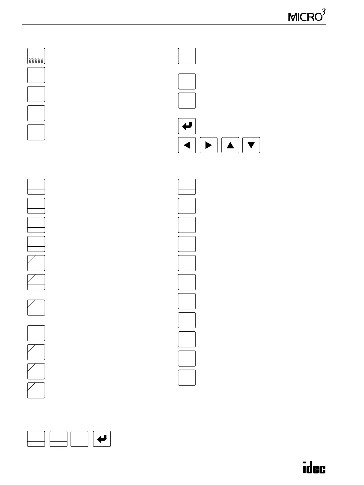
Function Keys
Program Keys
Program keys have one or more legends or numbers on the key top. These keys select the operation automatically depend-
ing on the preceding key. For example, when the following keys are pressed in sequence:
The first key selects “LOD” to start key sequence.
The second key selects “Input” because “SET” does not follow “LOD.”
The third key selects “1” because “BPS” does not follow “I.”
ADV
CLR
DEL
ADRS
MON
TRS
FUN
INS
Clear key used to return to the previous opera-
tion level or back to the editor mode.
Advance instruction key used to program advanced
instructions, to monitor high-speed counter, or to
monitor double-word data.
Cursor move keys used
to move the cursor or
read a program
Insert key used to insert a program instruction.
Delete key used to delete program instructions.
Address key used to select a program address.
Monitor key used to monitor the MICRO
3
oper-
ation, to change timer/counter preset value, or
to enter data into data register.
Function key used to change FUN table settings.
Transfer key used to transfer and compare user pro-
grams between the program loader and the MICRO
3
base unit or memory card.
Enter key used to write a program or FUN settings.
LOD
10
OUT
16
SET
I
TIM
T
AND
D
OR
E
D
RST
F
Q
CNT
C
SFR
R
SOT
C
M
NOT
A
REP
B
7
END
8
MCS/R
9
JMP/E
6
CC>=
3
BPP
5
CC=
2
BRD
4
1
BPS
0
Programs the LOD instruction.
Precedes entering a decimal value.
Programs the shift register instruction.
Specifies the shift register operand (R).
Programs the OUT instruction.
Precedes entering a hexadecimal value.
Programs or executes the SET instruction.
Specifies the input operand (I).
Programs the TIM, TMH, or TMS instruction.
Specifies the timer operand (T).
Enters hexadecimal value D.
Programs the AND instruction.
Enters hexadecimal value E.
Programs the OR instruction.
Specifies the data register operand (D).
Enters hexadecimal value F.
Programs or executes the RST instruction.
Specifies the output operand (Q).
Programs the counter instruction.
Specifies the counter operand (C).
Enters hexadecimal value A.
Programs the NOT instruction.
Enters hexadecimal value B.
Programs the repeat or selects an option.
Enters hexadecimal value C.
Programs the SOTU or SOTD instruction.
Specifies the internal relay operand (M).
Enters decimal or hexadecimal value 7.
Programs the END instruction.
Enters decimal or hexadecimal value 8.
Programs the MCS or MCR instruction.
Enters decimal or hexadecimal value 9.
Programs the JMP or JEND instruction.
Enters decimal or hexadecimal value 4.
Enters decimal or hexadecimal value 5.
Programs the CC= instruction.
Enters decimal or hexadecimal value 6.
Programs the CC≥ instruction.
Enters decimal or hexadecimal value 1.
Programs the BPS instruction.
Enters decimal or hexadecimal value 2.
Programs the BRD instruction.
Enters decimal or hexadecimal value 3.
Programs the BPP instruction.
Enters decimal or hexadecimal value 0.
LOD
10
SET
I
1
BPS