4: SPECIAL FUNCTIONS
USER’S MANUAL 4-3
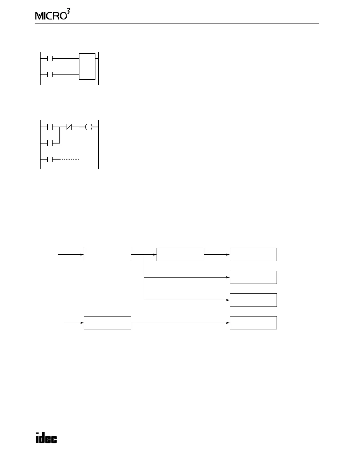
Example: Counting Catch Input Pulses
This example demonstrates a program to count short pulses using the catch input function.
Example: Maintaining Catch Input
When a catch input is received, a special internal relay assigned to the catch input is turned on for only one scan. This
example demonstrates a program to maintain a catch input status for more than one scan.
Input Filter Function
MICRO
3
features the input filter function to select the input pulse widths to read inputs I0 through I7. The input filter
ignores pulse inputs shorter than the selected value to prevent malfunction caused by noises.
Input filters are available in hard filter and soft filter. Both filters are selected using FUN7. High-speed counters and catch
inputs can use only the hard filter. Normal inputs I0 through I7 can use both hard and soft filters.
Filter Circuit Schematic
When hard filter is set at default value of 10, catch input and high-speed counter input values are shown below.
Minimum pulse width to accept catch input (ON pulse): Input I0 = 28 µsec, Inputs I1 to I7 = 37 µsec
Minimum pulse width to accept catch input (OFF pulse): Input I0 = 30 µsec, Inputs I1 to I7 = 120 µsec
High-speed counter input frequency: 10 kHz (HSC0 and HSC3), 5 kHz (HSC1 and HSC2)
Inputs I10 through I15 and all inputs I20 through I35 at the expansion station cannot use the hard filter and soft filter. Input
signals to these inputs are filtered by fixed filter of 3.0 msec. Short-pulse inputs and noises shorter than 3.0 msec are ignored.
Note: Normal inputs I0 through I35 require 1 scan time in addition to the applicable hard, soft, or fixed filter value to accept
input signals.
M290
I1
C2
100
Reset
Pulse
Input I1 is used as a reset input for adding counter C2.
Input I0 is assigned to catch input special internal relay M290.
Counter C2 counts short-pulse inputs to input I0.
Note: When catch inputs M290 through M297 are used as pulse inputs to a counter, the
repeat cycle periods of the pulse inputs must be more than 2 scan times.
M0
M290
Input I0 is assigned to catch input special internal relay M290.
When input I0 is turned on, M290 is turned on, and M0 is maintained in the self-holding
circuit.
When NC input I1 is turned on, the self-holding circuit is unlatched, and M0 is turned off.
M0 is used as an input condition for the subsequent program instructions.
M0
I1 M0
Inputs
Hard Filter Soft Filter
Normal Inputs
I0 to I7
Catch Inputs
M290 to M297
High-speed Counter
I0
Normal Inputs
I10 to I35
Default: 3 msecDefault: 10
Fixed Filter
I0 to I7
Inputs
I10 to I35
FUN7 H: 0 to 255 FUN7: 0, 3, 7, or 10 msec
For groups G1 to G4
Filter value: 3 msec (fixed)