1: GENERAL INFORMATION
USER’S MANUAL 1-21
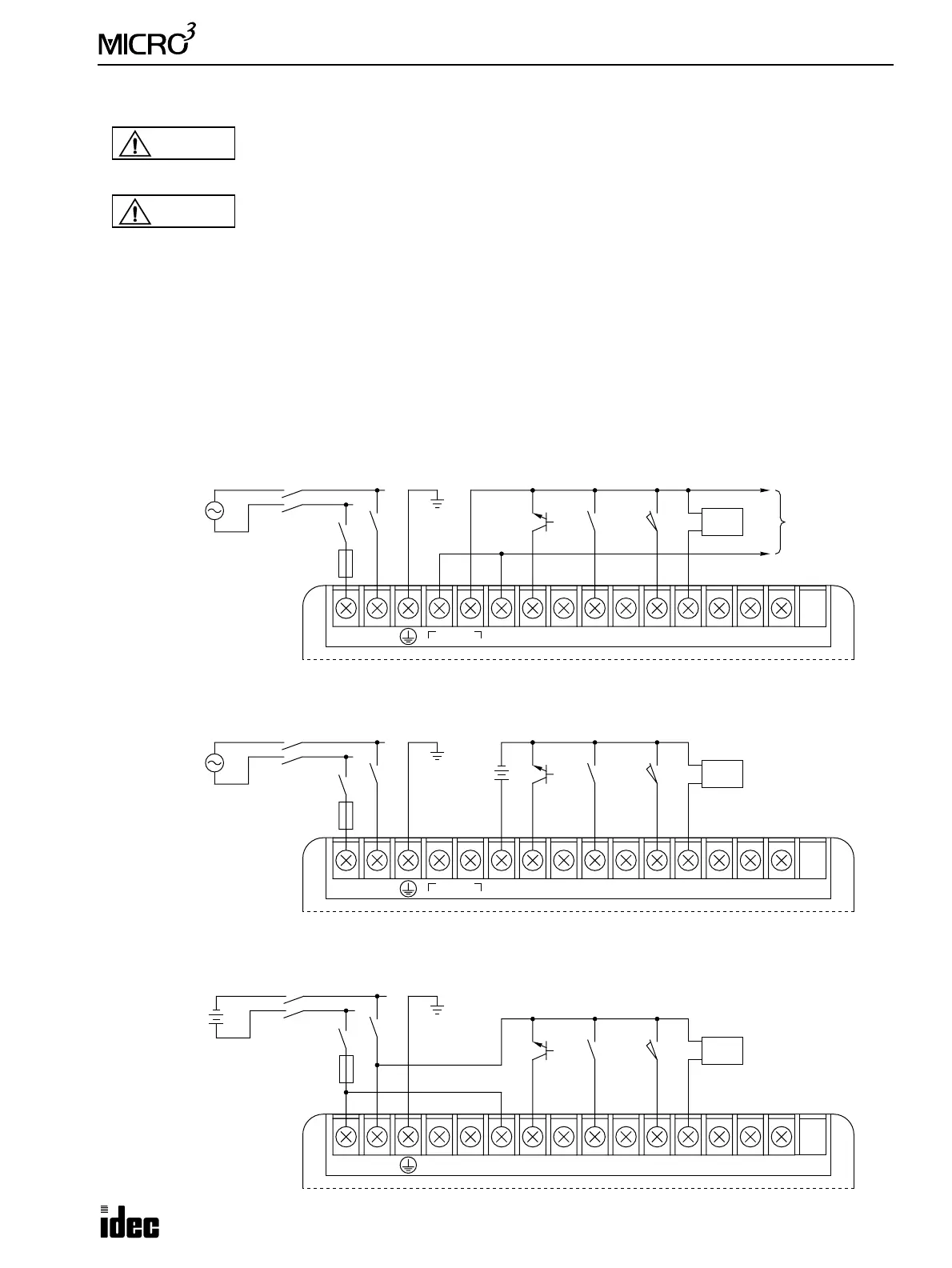
Input Wiring Diagrams
DC Source Input (AC Power Type)
• When using the sensor power supply from the DC OUT terminals
• When using an external power supply
DC Source Input (DC Power Type)
Warning
• Emergency and interlocking circuits must be configured outside the MICRO
3
. If such a circuit is
configured inside the
MICRO
3
, failure of the MICRO
3
may cause disorder of the control system,
damage, or accidents.
Caution
• Use a power supply of the rated value. Use of a wrong power supply may cause fire hazard.
• Use an IEC127-approved fuse on the power line outside the MICRO
3
. This is required when
exporting equipment containing MICRO
3
to Europe.
• Use an EU-approved circuit breaker. This is required when exporting equipment containing
MICRO
3
to Europe.
• Do not connect to the ground directly from the MICRO
3
. Connect a protective ground to the equip-
ment containing MICRO
3
using an M4 or larger screw. This is required when exporting equipment
containing MICRO
3
to Europe.
• If relays or transistors in the MICRO
3
output circuit fail, outputs may remain on or off. For output
signals which may cause heavy accidents, provide a monitor circuit outside of the MICRO
3
.
• Use an IEC127-approved fuse on the output circuit. This is required when exporting equipment
containing MICRO
3
to Europe.
100-240V AC
Sensor
Ground
100-240V AC
LN
DC OUT
24V 0V
DC IN
COM
0123456710
2-wire
Sensor
+
–
N
L
Main Power
Switch
Sw
3A Fuse
NPN
Transistor
–
+
Ground
100-240V AC
LN
DC OUT
24V 0V
DC IN
COM
0123456710
External
Power
24V DC
100-240V AC
N
L
Main Power
Switch
Sw
3A Fuse
2-wire
Sensor
+
–
NPN
Transistor
Main Power
Switch
24V DC
+–
DC IN
COM
0123456710
External
Power
24V DC
–
+
NC NC
3A Fuse
Ground
2-wire
Sensor
+
–
NPN
Transistor
Sw