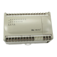
USER’S MANUAL 1-1
1: GENERAL INFORMATION
Introduction
This chapter describes general information for understanding MICRO
3
functions and specifications.
Features
MICRO
3
is a space-saving micro programmable controller, yet has high-performance functions described below:
High-speed Processing Function
MICRO
3
operates in standard processing mode or high-speed processing mode. Standard mode has a program capacity of
1012 steps, minimum processing time of 1.2 µsec per basic instruction, and average scan time of 2.9 msec for 1,000 steps.
High-speed processing mode has a program capacity of 100 steps, minimum processing time of 0.2 µsec per basic instruc-
tion, and average scan time of 400 µsec for 100 steps. Data and expansion link cannot be used with high-speed processing.
Catch Input Function
The catch input function makes sure to receive short input pulses (40 µsec minimum at the rising edge) from sensors with-
out regard to the scan time.
The 10-I/O type MICRO
3
base unit can receive short pulse inputs at 6 input terminals (I0 through I5). The 16- and 24-I/O
type base units can use 8 input terminals (I0 through I7) for catch inputs.
Input Filter Function (DC Input Type Only)
The input filter can be adjusted for input signal durations. This function is useful for adjusting the input pulse width in sen-
sor controller applications and for eliminating input noises and chatter in limit switches.
High-speed Counter Function
MICRO
3
has a built-in high-speed counter to make it possible to count up to 4,294,967,295 (FFFF FFFFh) high-speed
pulses which cannot be counted by the normal user program processing. The maximum count input frequency is 10 kHz.
This function can be used for simple positioning control and simple motor control.
Pulse Output Function
Pulse outputs can be generated using advanced instructions. The PULS (pulse output) instruction can vary the output fre-
quency at a fixed duty ratio of 50%. This instruction can be used in combination with the high-speed counter function to
control servo motors and stepper motors. The PWM (pulse width modulation) instruction can change the duty ratio at a
fixed frequency. This instruction can be used for illumination control.
Computer Link Function
A personal computer can be connected to MICRO
3
in 1:1 peer-to-peer or 1:N network communication system to monitor
the operating statuses and change data in MICRO
3
. CUBIQ software is available for easy programming and monitoring.
Expansion Link Function
The I/O points can be expanded from 6 inputs and 4 outputs up to 28 inputs and 20 outputs by connecting another MICRO
3
in six combinations, maximizing flexibility, (see note).
Data Link Function
A maximum of seven MICRO
3
base units (1 master station and 6 slave stations) can be linked in the data link network for
distributed control. FA-3S high-performance CPU can also be used as a master station in the data link system (see note).
Real-time Clock/Calendar Function (16- and 24-I/O Type Units Only)
The 16- and 24-I/O type MICRO
3
base units feature a real-time clock/calendar to program year, month, day, day of week,
hour, minute, and second using advanced instructions. This function can be used for time-scheduled control of illumina-
tion, air conditioners, sprinklers, and many others.
External Analog Timer
MICRO
3
is equipped with one or two analog potentiometers to enter analog values. In addition, a separate analog timer unit
can also be connected to MICRO
3
, allowing for fine adjustment of timer preset values on the control panel.
User Program Read and/or Write Protection
User programs in the MICRO
3
base unit can be protected from reading and/or writing by setting a pass word. This function
is ideal for the security of user programs and prevention of inadvertent rewriting of programs.
Analog I/O Function
A/D and D/A converter units are available for 8-bit conversion to process analog signals.
Note: Expansion link and data link cannot be used concurrently.

 Loading...