7: BASIC INSTRUCTIONS
7-2 USER’S MANUAL
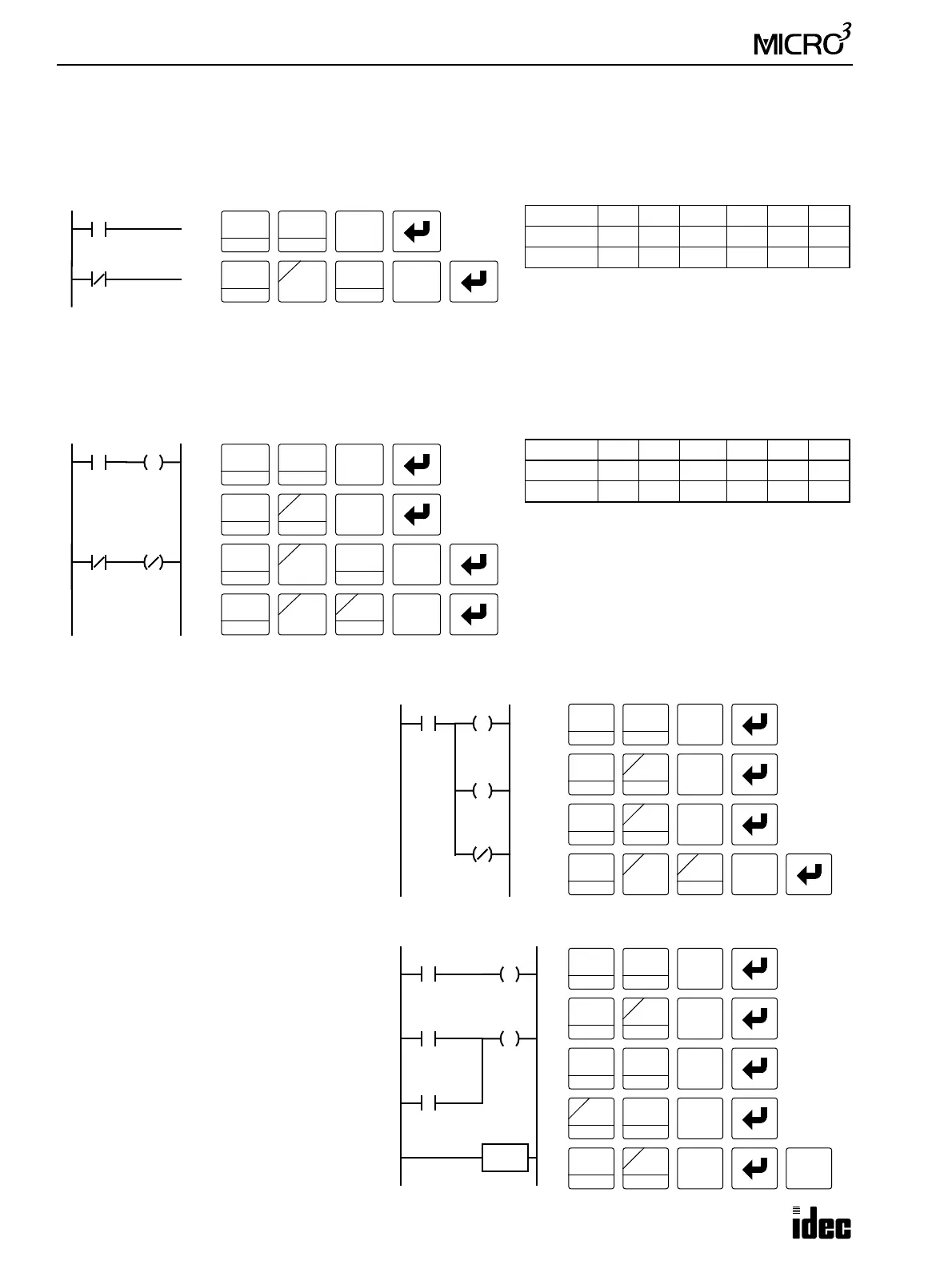
LOD (Load) and LODN (Load Not)
The LOD or LODN instruction is used before an operand starting at the left bus of the ladder diagram. The LOD instruc-
tion starts the logical operation with an NO (normally open) contact. The LODN instruction starts the logical operation
with an NC (normally closed) contact. Eight LOD and LODN instructions can be used consecutively.
OUT (Output) and OUTN (Output Not)
The OUT instruction outputs the result of bit logical operation to the specified operand. The OUTN instruction outputs the
inverted result of bit logical operation to the specified operand.
Multiple OUT and OUTN
There is no limit to the number of OUT and
OUTN instructions that can be programmed
into one rung.
Programming multiple outputs of the same
output number is not recommended. However,
when doing so, it is good practice to separate
the outputs with the JMP/JEND set of instruc-
tions, or the MCS/MCR set of instructions.
These instructions are detailed later in this
chapter.
When the same output address is programmed
more than once with one scan, the output
nearest to the END instruction is given prior-
ity for outputting. In the example on the right,
output Q0 is off.
Ladder Diagram Key Operation
I0
I1
LOD
10
SET
I
NOT
A
1
BPS
0
LOD
10
SET
I
Valid Operands (Standard Processing)
When using in the high-speed processing mode,
operands are limited. See page 6-1.
Instruction
IQMTCR
LOD 0-35 0-31 0-317 0-31 0-31 0-63
LODN 0-35 0-31 0-317 0-31 0-31 0-63
Ladder Diagram Key Operation
I2
I3
LOD
10
SET
I
NOT
A
1
BPS
LOD
10
SET
I
Q1
Q0
OUT
16
RST
F
Q
0
3
BPP
2
BRD
OUT
16
NOT
A
RST
F
Q
Valid Operands (Standard Processing)
When using in the high-speed processing mode,
operands are limited. See page 6-1.
Instruction
IQMTCR
OUT — 0-31 0-287 — — —
OUTN — 0-31 0-287 — — —
Ladder Diagram Key Operation
I1
LOD
10
SET
I
1
BPS
Q2
Q0
OUT
16
RST
F
Q
0
2
BRD
OUT
16
NOT
A
RST
F
Q
Q1
0
OUT
16
RST
F
Q
Ladder Diagram Key Operation
I1
LOD
10
SET
I
Q0
OUT
16
RST
F
Q
0
2
BRD
OUT
16
RST
F
Q
Q0I2
I3
END
SET
I
OR
E
D
1
BPS
LOD
10
SET
I
3
BPP
0
7
END
ON state
OFF state
OFF state