4: SPECIAL FUNCTIONS
USER’S MANUAL 4-21
Analog Input Function
The A/D converter unit is used with MICRO
3
to perform an 8-bit A/D conversion. The A/D converter unit reads analog
input signals from an analog output device such as an analog distance sensor. The output from the A/D converter unit is
entered to MICRO
3
input I0 and converted into a digital value 0 through 249 using the A/D (analog/digital conversion)
instruction. If the input to the A/D converter unit exceeds the input range, an overflow occurs and 250 is set to the destina-
tion operand of the A/D instruction. Only one A/D converter unit can be connected to the MICRO
3
base unit.
Note: When the A/D converter unit is connected to MICRO
3
, the HSC (high-speed counter) function cannot be used.
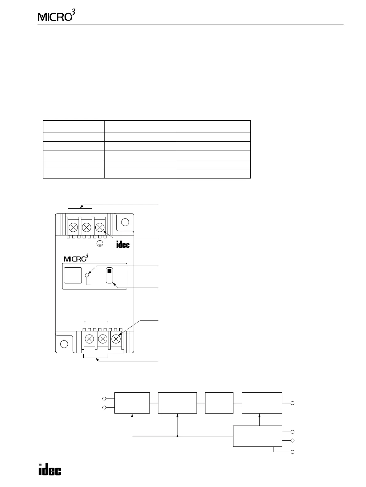
A/D Converter Unit
Depending on the input signals, five A/D converter units are available:
Parts Description
Internal Circuit
Type No. Input Signal Range Remarks
FC2A-AD1 0 to 5V DC
FC2A-AD2 0 to 10V DC
FC2A-AD3 –5 to 5V DC
FC2A-AD4 4 to 20mA DC Input resistance 250Ω
FC2A-AD5 –10 to +10V DC
+–
24V DC
A/D UNIT
INPUT
4-20mA
POWER
SINK
SCE
+–
ANALOG WIRE TO
IN 0
INPUT OUTPUT
Power Supply Terminals
Connect power supply 24V DC.
FG Terminal
Connect to the ground. (Grounding resistance 100Ω maximum)
Power Indicator
Turns on when power is supplied.
Output Selector Switch
Select the sink or source output depending on the MICRO
3
input.
Set to SINK when connecting the output to the source MICRO
3
input.
Set to SCE when connecting the output to the sink MICRO
3
input.
Output Terminal
Connect to the input 0 terminal on the MICRO
3
.
Analog Input Terminals
Connect analog input signal.
+24V DC
OUTPUT
–24V DC (GND)
FG
DC/DC Converter
Output Circuit
Sink or Source
Isolation
Circuit
Operation
Circuit and
V/F Converter
Differential
Amplifier
ANALOG INPUT +
ANALOG INPUT –