14: CLOCK / CALENDAR INSTRUCTIONS
USER’S MANUAL 14-3
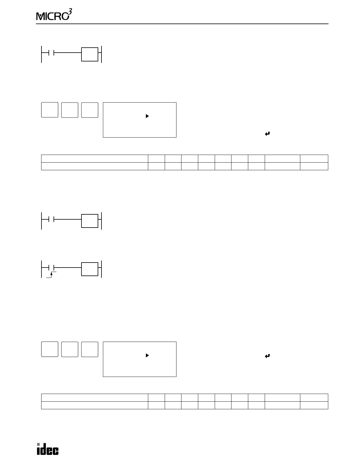
73 CLKR (Clock Read)
Key Operation
Valid Operands (Standard Processing)
In the high-speed processing mode, data registers for this instruction are limited to D0 through D31.
Since the CLKR instruction is executed in each scan while input is on, a pulse input from an SOTU or SOTD instruction
should be used as required.
Example: CLKR
74 CLKW (Clock Write)
Note: If time is assigned a value which is not within the range specified above, invalid data will result in a user program
execution error, internal relay M304 turns on, and the ERR1 indicator on the MICRO
3
base unit also turns on. The error
code is stored in data register D93 when the control data register is enabled using FUN10. See page 5-8.
Key Operation
Valid Operands (Standard Processing)
In the high-speed processing mode, data registers for this instruction are limited to D0 through D31.
Since the CLKW instruction is executed at the rising edge of the input, a pulse input from an SOTU or SOTD instruction
is not required.
Operand Function I Q M T C R D Constant Repeat
Destination to read the clock data ——————0-99 — —
Operand Function I Q M T C R D Constant Repeat
Destination to write the clock data ——————0-99 — —
When input is on, clock data (hour, minute, and second) is read to three data registers start-
ing with the designated operand.
D = Hour (0 to 23)
D+1 = Minute (0 to 59)
D+2 = Second (0 to 59)
CLKR
****
ADV
0 LOD I 0
1 CLKR
3 END
4 END
7
END
3
BPP
Enter operand for the first data register to read clock data.
Three consecutive data registers are required to read the
clock data.
To enter the instruction, press the key.
I2
When input I2 is on, clock data is read to data registers D50 through D52.
D50 = Hour (0 to 23)
D51 = Minute (0 to 59)
D52 = Second (0 to 59)
CLKR
D50
When input is turned on, the clock is set using data stored in three data registers starting with
the designated operand.
D = Hour (0 to 23)
D+1 = Minute (0 to 59)
D+2 = Second (0 to 59)
CLKW
****
ADV
7
END
4
Enter operand for the first data register to write clock data.
To enter the instruction, press the key.
Store clock data to three consecutive data registers starting
with the designated operand.
0 LOD I 0
1 CLKW
3 END
4 END